Aerofoil Geometry
Aerofoil geometry is the set of terms that describe the shape of a wing or blade section, namely its chord line, camber and thickness, and the angles, angle of attack and angle of incidence, that describe how the section meets the airflow and how it is fixed to the aeroplane.
An aerofoil, spelt airfoil in the United States, is a body shaped to produce an aerodynamic reaction at right angles to its motion through the air without excessive drag. Wings, tailplanes, fins, propeller blades and helicopter rotor blades are all aerofoils. A slice through any of them, taken in the direction of the airflow, shows an aerofoil section, the profile whose shape decides how the surface behaves.
Two groups of terms describe it. The first describes the shape: the chord line, camber and thickness. The second describes how the section meets the air and how it is fixed to the aeroplane: angle of attack and angle of incidence. Together with dynamic pressure and area they set the lift through the lift coefficient, which at low speed depends mainly on the shape of the section and its angle of attack (see lift). The vocabulary is precise, and exam questions test the differences between terms that sound alike.
Parts of an aerofoil
- The leading edge (LE) is the rounded front of the section, where the oncoming air divides at the stagnation point to pass above and below. Its roundness is described by the leading-edge radius.
- The trailing edge (TE) is the sharp rear edge, where the flows from the two surfaces leave the section. The sharp edge fixes how the flow leaves the wing, and with it the lift the section produces.
- The upper surface and lower surface join the two, and the greatest distance between them is the maximum thickness.
Chord line and camber
The chord line is the straight line joining the leading and trailing edges. EASA exam material defines it as the straight line joining the centres of curvature of the leading and trailing edges; the FAA describes it simply as an imaginary straight line from the leading edge to the trailing edge. The chord is its length. On a tapered wing the chord varies along the span, and a representative figure, the mean aerodynamic chord, is used for stability and centre of gravity limits (see centre of gravity).
The mean camber line is the line joining the leading and trailing edges midway between the upper and lower surfaces at every point. Camber is the curvature of that line. Maximum camber is its greatest distance from the chord line, expressed as a percentage of the chord, and its position is given as a percentage of the chord aft of the leading edge. With positive camber the mean camber line lies above the chord line; with negative camber it lies below.
Camber is one of the main factors that determine the lift a section can give. Increasing it raises the lift coefficient at a given angle of attack and raises the maximum lift coefficient, CLmax. A cruise wing uses modest camber for low drag at speed, and high-lift devices add camber for take-off and landing: a flap is a hinged part of the wing that is deflected to increase camber, and a Fowler flap increases both camber and wing area.
Thickness/chord ratio
The thickness/chord ratio is the maximum thickness of the section expressed as a percentage of its chord, with the position of maximum thickness given as a percentage of the chord aft of the leading edge. A section 0.24 m thick with a chord of 2 m has a thickness/chord ratio of 12 %. It is also called relative thickness.
It has a great influence on the airflow. A thicker section gives a deeper structure, lighter for the same strength, and more room for fuel, but it accelerates the flow more over the upper surface. At high speed that brings the local flow to Mach 1 sooner, so increasing the thickness/chord ratio lowers the critical Mach number. High-speed wings are therefore thin, swept, or built with supercritical sections that tolerate greater thickness (see high-speed flight).
Symmetrical and cambered sections
A symmetrical aerofoil has upper and lower surfaces that are mirror images, so its mean camber line and chord line coincide and it has no camber. At zero angle of attack the flows over the two surfaces are identical and it produces no lift. Within the normal range of angle of attack its centre of pressure does not move, and it has no pitching moment about its aerodynamic centre. It suits surfaces that must lift equally well in either direction, such as fins.
A cambered aerofoil is the normal choice for wings. It produces lift at zero angle of attack and reaches zero lift only at a small negative angle, typically about −4°. As the angle of attack increases its centre of pressure moves forward, reaching its most forward position just before the stall, and then moves sharply aft as the wing stalls. About its aerodynamic centre, near 25 % of the chord, a positively cambered section has a constant nose-down pitching moment.
| Symmetrical section | Positively cambered section | |
|---|---|---|
| Mean camber line | Coincides with chord line | Above the chord line |
| Lift at zero angle of attack | None | Positive |
| Zero-lift angle of attack | 0° | Small negative angle, about −4° |
| Centre of pressure as angle of attack rises | Stays put | Moves forward, then aft at the stall |
| Pitching moment about aerodynamic centre | Zero | Nose-down |
Aft loading
Aft loading, or rear loading, is a pressure distribution in which an unusually large share of the lift is produced over the rear part of the chord. It comes from strong positive camber near the trailing edge, and it is the hallmark of the supercritical aerofoil used on modern jet transports. Such a section has a large leading-edge radius, a relatively flat upper surface, an S-shaped camber line and a comparatively thick trailing edge. The flat upper surface limits the acceleration of the flow, so shock waves form at a higher free-stream Mach number and are weaker; the camber near the trailing edge recovers the lift the flat top gives up.
Aft loading has two costs. Lift concentrated towards the trailing edge gives a large nose-down pitching moment, which the tailplane must balance with a download, adding trim drag. The forward part of the section, with little or even negative camber, also gives a lower CLmax at low speed, so supercritical wings need powerful high-lift devices.

Angle of attack
The angle of attack (AoA), α, is the angle between the chord line and the relative airflow. EASA texts also call it the aerodynamic incidence; the FAA defines it as the acute angle between the chord line and the relative wind. Because the relative airflow is parallel and opposite to the flight path, angle of attack depends on where the aeroplane is going, not only on where it is pointing.
Angle of attack is the pilot's control of the lift coefficient. In level flight each indicated airspeed at a given weight needs its own angle of attack: lower when faster, higher when slower. Some reference values for a typical section, as exam texts give them:
- Zero lift: 0° for a symmetrical section, about −4° for a cambered one.
- Best lift/drag ratio: about 4°, the optimum for cruise.
- Critical (stalling) angle: about 16°, where CLmax is reached; FAA material quotes about 16° to 18°. It is fixed for a given wing and configuration and is not changed by weight, bank or airspeed, although above about M 0.4 compressibility lowers it (see stall).
On a real wing the downwash from the tip vortices tilts the airflow at the wing, so the effective angle of attack is less than the geometric angle between chord and free stream (see induced drag and wingtip vortices).
Angle of incidence
The angle of incidence is the angle between the wing root chord line and the aeroplane's longitudinal axis. It is built into the structure and fixed for the wing, though it may be variable for a tailplane that is moved to trim, the trimmable horizontal stabiliser. The FAA uses the term in the same sense. It is not the same as angle of attack, and exam questions play on the resemblance between angle of incidence and aerodynamic incidence.
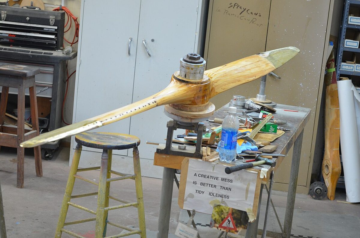
Incidence need not be constant along the span. With washout, the angle of incidence decreases from root to tip, so the root reaches its stalling angle first while the outer wing and ailerons keep working. Propeller blades carry the idea further: the blade angle, between the blade chord line and the plane of rotation, decreases from hub to tip because the tip travels faster, keeping the blade's angle of attack roughly the same along its length (see propeller aerodynamics).
Angle of attack versus pitch attitude
Pitch attitude is the angle between the aeroplane's longitudinal axis and the horizon. It is what the pilot sees and what the attitude indicator shows; angle of attack is not directly visible. The two are linked through the flight path. The angle of attack of the fuselage axis is the wing's angle of attack minus the angle of incidence, and the pitch attitude is the flight path angle plus that fuselage angle of attack. Take a wing set at 2° of incidence, flying at 6° angle of attack:
- In level flight the pitch attitude is 6° − 2° = 4° nose-up.
- Climbing at a 5° flight path angle with the same angle of attack, it is 4° + 5° = 9° nose-up.
- Descending at 3°, it is 4° − 3° = 1° nose-up.
The consequences are practical. A nose-high attitude does not by itself mean a high angle of attack, and a nose-low attitude does not protect against the stall: an abrupt pull-out from a dive can reach the critical angle with the nose below the horizon. With flap extended the wing reaches its critical angle at a lower nose attitude, which can mislead a pilot into thinking there is margin left. Swept-wing jets, whose lift curve is shallower, fly noticeably nose-high on the approach.
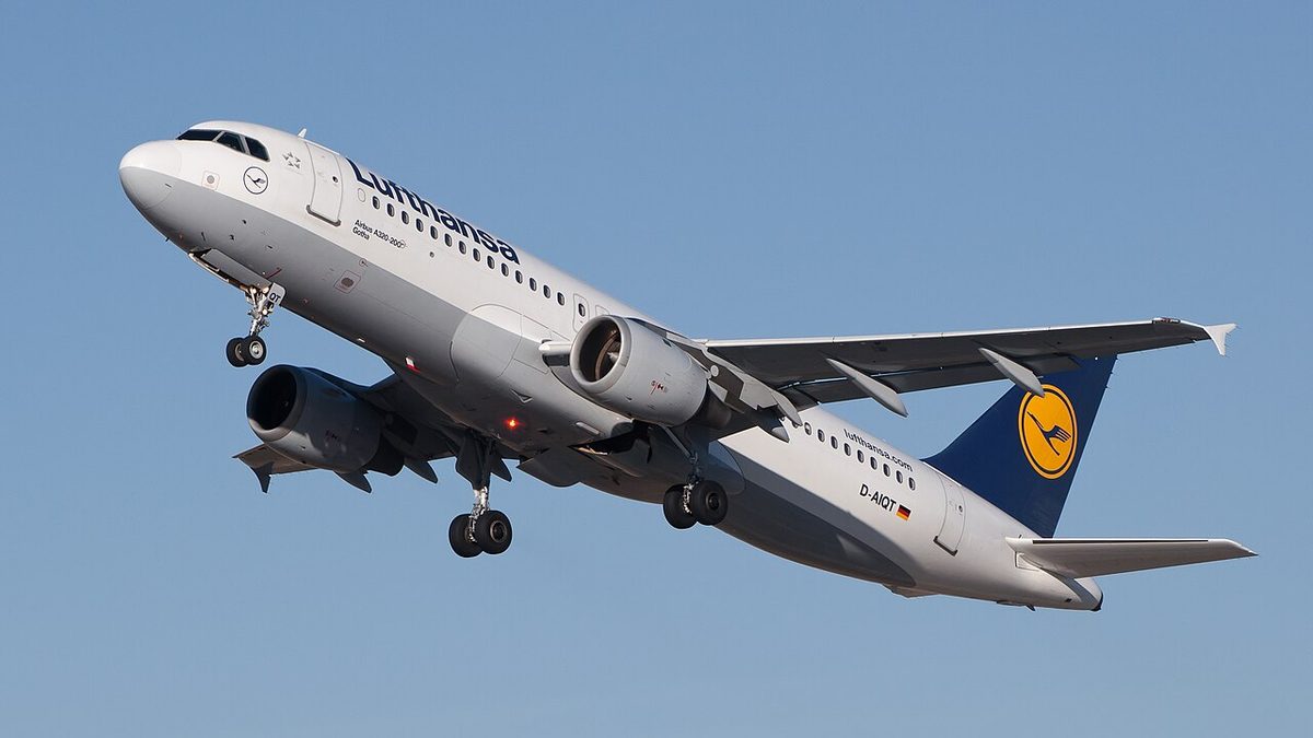
Attitude is nonetheless the pilot's primary reference, because a known pitch attitude with a known power setting gives predictable performance. Airliners fly target attitudes in the windshear escape manoeuvre, typically an initial 15°, raised towards the pitch limit indicator if needed, and fly memorised pitch and thrust settings when airspeed indications become unreliable. On the ground, attitude is limited by geometry: rotating too early or too fast can raise the attitude beyond the tail clearance angle before lift-off, about 11° to 13° for many narrowbodies, and cause a tail strike.
Exam tip: angle of attack is chord to relative airflow; angle of incidence is root chord to longitudinal axis; pitch attitude is longitudinal axis to horizon. Only angle of attack decides whether the wing stalls.
Frequently asked questions
What is the chord line of an aerofoil?
The chord line is the straight line joining the leading and trailing edges of an aerofoil section. EASA exam material defines it precisely as the line joining the centres of curvature of the leading and trailing edges; the FAA describes it as an imaginary straight line from the leading edge to the trailing edge. The chord is its length. The chord line is the reference for the angle of attack, camber and thickness.
What is the difference between angle of attack and angle of incidence?
Angle of attack is the angle between the chord line and the relative airflow. It changes continuously in flight and controls the lift coefficient. Angle of incidence is the angle between the wing root chord and the aeroplane's longitudinal axis, fixed when the wing is built. EASA texts also call the angle of attack the aerodynamic incidence, so the phrase angle of incidence on its own means the rigging angle.
What is camber on a wing?
Camber is the curvature of an aerofoil section. It is measured by the mean camber line, which runs from leading edge to trailing edge midway between the upper and lower surfaces. Maximum camber is its greatest distance from the chord line, given as a percentage of the chord, with its position as a percentage of the chord aft of the leading edge. More camber raises the lift coefficient and its maximum.
Is a high nose attitude the same as a high angle of attack?
No. Pitch attitude is measured from the horizon, angle of attack from the relative airflow, which follows the flight path. In a steep climb the nose can be high with a modest angle of attack, while in an abrupt pull-out from a dive the nose can be below the horizon with the wing at its critical angle. That is why a wing can stall at any attitude and any airspeed.
Why does a symmetrical aerofoil give no lift at zero angle of attack?
A symmetrical section has its upper and lower surfaces as mirror images, so its mean camber line and chord line coincide. At zero angle of attack the flow over both surfaces is the same and the pressures cancel. It produces lift only when inclined to the airflow, positive or negative, and its centre of pressure stays in place, which suits surfaces such as fins that must lift equally in either direction.
What is aft loading on an aerofoil?
Aft loading is a pressure distribution in which an unusually large share of the lift is produced over the rear of the chord, created by strong camber near the trailing edge. It is typical of supercritical sections, whose flat upper surface keeps shock waves weak at high Mach number. The price is a large nose-down pitching moment, which the tailplane must balance at the cost of trim drag.
Test yourself on Aerofoil Geometry
The v1prep banks cover this topic in Principles of Flight (081), with a worked explanation for every answer. EASA ATPL, PPL, IR and CPL, the FAA written tests and A320/B737 type ratings.
Start practising →Sources and further reading
- FAA Pilot's Handbook of Aeronautical Knowledge (FAA-H-8083-25), Chapters 4 and 5, Principles and Aerodynamics of Flight
- FAA Airplane Flying Handbook (FAA-H-8083-3C), Chapter 5, Maintaining Aircraft Control
- EASA, Explanatory Note to ED Decision 2018/001/R, Part-FCL theoretical knowledge learning objectives
- NASA, Where Are They Now, F-8 Supercritical Wing
- Scholz, D., Mach number, relative thickness, sweep and lift coefficient of the wing (HAW Hamburg)
Library articles are written for study and exam preparation. They do not replace your aircraft's approved documentation, your operator's procedures or the regulations themselves.