High-Lift Devices
High-lift devices are movable surfaces on the leading and trailing edges of a wing, such as flaps, slats and slots, that raise its maximum lift coefficient so that the aeroplane can fly safely at the low speeds needed for take-off, approach and landing.
High-lift devices are the movable surfaces that change a wing's shape for low-speed flight: flaps on the trailing edge and, on most jets, slats, slots or Krueger flaps on the leading edge. A wing designed for efficient cruise has modest camber and a size chosen for cruise, so on its own it would need a very high speed to lift the aeroplane at take-off and landing. High-lift devices raise the maximum lift coefficient when it is needed and are retracted afterwards, leaving the clean configuration.
For pilots they matter because every one of them changes the stall speed, the attitude, the drag, the pitch trim and the speed limits. Selecting the right setting, and retracting it at the right speed, is part of every take-off, approach and go-around.
Why high-lift devices are needed
In level flight the stall speed is VS = √(2W ÷ (ρ × S × CLmax)), from the lift equation. For a given weight, the only ways to lower it are a larger wing area S or a higher maximum lift coefficient CLmax. High-lift devices provide both. Their primary purpose is to reduce take-off and landing distances by increasing the usable CLmax, which also allows greater weights from a given runway.
The gain is multiplied through the operating speeds. For large aeroplanes certified under CS-25 and 14 CFR Part 25, V2 must be at least 1.13 VSR and VREF at least 1.23 VSR0, multiples of the 1 g reference stall speed, so more flap means a lower stall speed and lower take-off and approach speeds (see take-off speeds). On landing, the energy to be absorbed varies with the square of the touchdown speed, so a lower threshold speed shortens the ground roll markedly.
High-lift devices work in two ways:
- Changing the section. Flaps increase camber, and some increase wing area as well.
- Controlling the boundary layer. Slots and slats feed high-energy air over the upper surface and delay separation to a higher angle of attack.
Most jet transports carry both leading-edge and trailing-edge devices. Light aeroplanes usually have trailing-edge flaps only. Wings with supercritical sections, optimised for high subsonic cruise, have a reduced CLmax at low speed and depend on extensive high-lift systems.
Trailing-edge flaps: plain, split and slotted
A flap is a hinged portion of the wing that can be deflected to increase camber. The simple types are:
- Plain flap. The rear of the wing hinges down as a unit. Simple, with a good increase in CLmax but fairly high drag. It is common on light, low-speed aeroplanes.
- Split flap. Only the lower surface of the trailing edge deflects; the upper surface contour is unchanged. It gives about the same lift as a plain flap, slightly more at high angle of attack, but the deepest wake and therefore the highest drag of the common types.
- Slotted flap. As it lowers, a gap opens between wing and flap. Higher-pressure air from below flows through the slot over the flap's upper surface, re-energises the boundary layer and keeps the flow attached at larger deflections. It gives a bigger increase in CLmax than a plain or split flap, with much less drag.
| Flap type | How it works | CLmax gain | Drag |
|---|---|---|---|
| Plain | Rear of the wing hinges down | Good | Fairly high |
| Split | Lower surface hinges down | About as plain | Highest |
| Slotted | Hinges down and opens a slot | Larger | Much lower than plain |
| Fowler | Moves aft, then down, usually slotted | Largest | Least for the lift gained |
Fowler flaps and multiple slots
The Fowler flap first moves rearwards on tracks, increasing wing area, and then deflects downwards, increasing camber. It is usually slotted, and large transports use single, double or triple-slotted versions. The combination of more area and more camber gives the greatest CLmax increase of the common types, with the least drag for the lift gained. The tracks sit inside the canoe-shaped fairings visible under an airliner's wing.
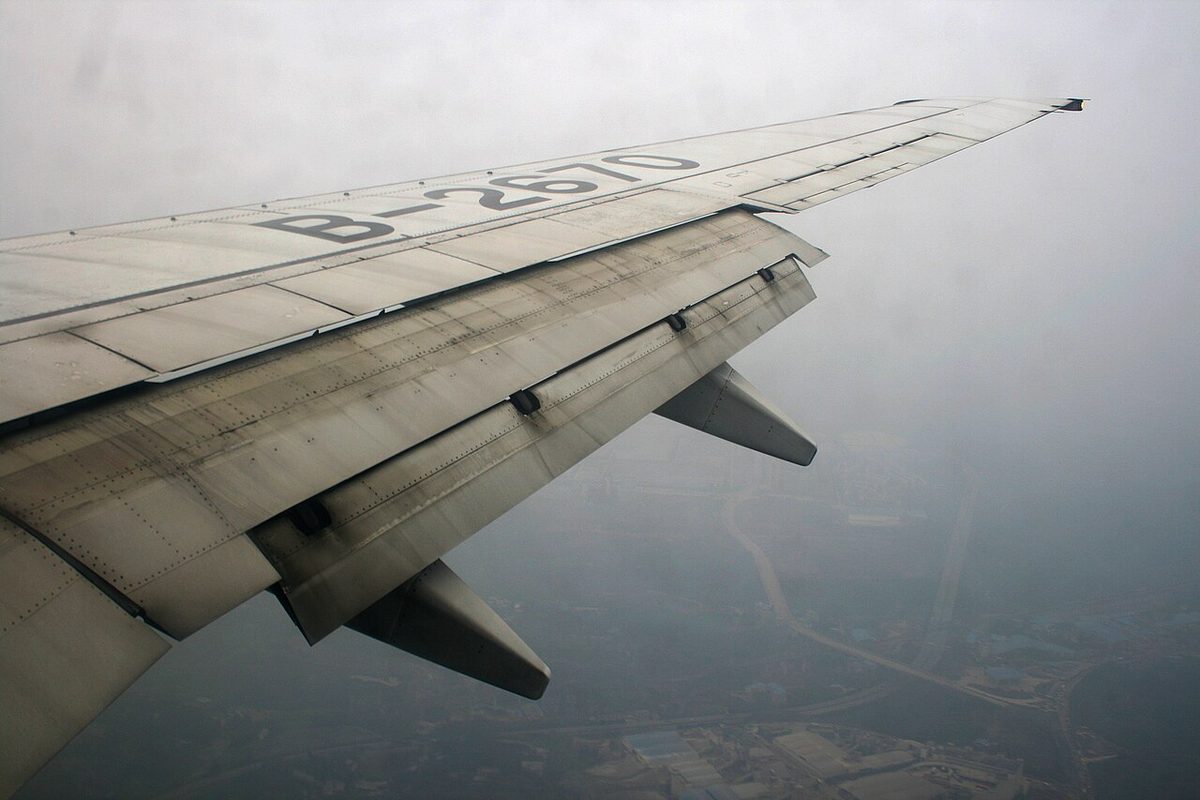
With any flap, the first degrees of deflection bring mostly lift and the last ones mostly drag: the lift increment per degree falls as the angle grows, while the drag increment rises. Small settings are therefore used for take-off, where drag hurts the climb, and large settings for landing, where drag helps.
Leading-edge slats and slots
A leading-edge slat is a small auxiliary aerofoil at the front of the wing. Extended, it moves forward and down and opens a slot. High-pressure air from below the wing flows through the slot, adds energy to the upper-surface boundary layer and delays separation. The stalling angle of attack increases markedly, to about 25° against about 16° for the basic section in ATPL texts, and CLmax rises as well. Slats produce only small changes in drag and pitching moment.
A leading-edge slot is a fixed duct built into the wing behind the leading edge. It works the same way but is always open. Slots are often fitted to the outboard wing ahead of the ailerons, so that the tips keep flying after the root has stalled, which preserves aileron control and gives a gentler stall.
Automatic slats on some light aeroplanes need no pilot action. At low angle of attack the high pressure near the stagnation point holds them closed; at high angle of attack suction over the slat pulls it forward and opens the slot. Transports achieve a similar effect with systems: on the Boeing 737, at flap positions 1, 2 and 5, the autoslat function drives the slats to full extension as the aeroplane approaches the stall, before the stick shaker operates.
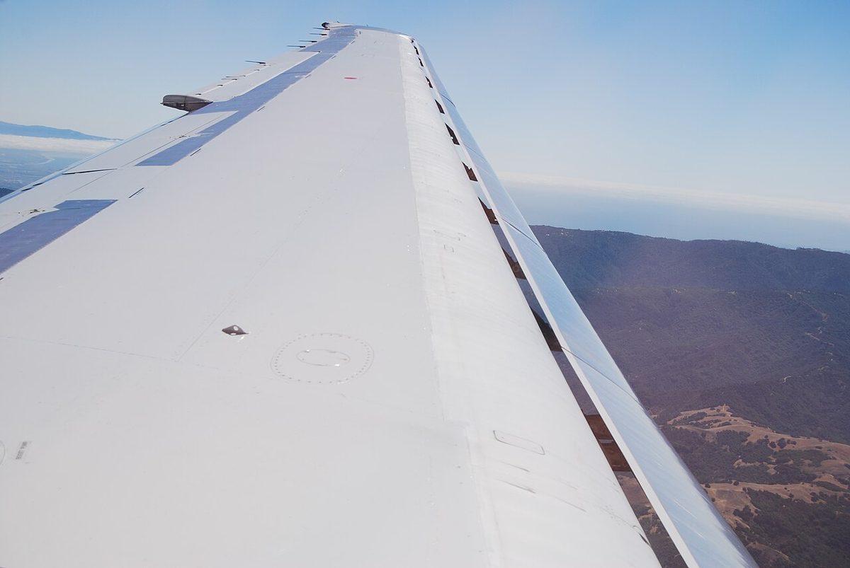
The price of a slat is attitude. Because it delays the stall rather than adding camber, the wing reaches its higher CLmax only at a much larger angle of attack, so the aeroplane flies nose-high at low speed and the pilot's view of the landing area is restricted. This is one reason slats are combined with trailing-edge flaps.
Krueger flaps and leading-edge droop
A Krueger flap is formed by part of the lower surface of the leading edge, hinged at its forward edge. It swings down and forward, increasing camber, leaves the upper surface unchanged and forms no slot. Krueger flaps are typically fitted to the inboard part of a swept wing to promote a root-first stall, with slats outboard, as on the Boeing 737 NG.
A leading-edge droop, or droop nose, hinges the whole nose section down to increase camber, again without a gap. A variable-camber flap is a flexible leading-edge panel that bends as it extends to increase camber smoothly; the Boeing 747 combines inboard Krueger flaps with variable-camber flaps outboard.
On aeroplanes with both leading-edge and trailing-edge devices, the leading-edge devices extend first and retract last. Lowering trailing-edge flap increases the upwash at the leading edge, which could stall an unprotected leading edge at high angle of attack.
Effects on CLmax, stall angle and pitch
| Effect | Trailing-edge flap | Leading-edge slat or slot |
|---|---|---|
| CLmax | Increases | Increases |
| Stalling angle of attack | Decreases | Increases markedly |
| Drag | Increases, steeply at large angles | Small change |
| Pitching moment | Significant, nose-up or nose-down by type | Small |
| Attitude at a given speed | Lower nose | Higher nose near the stall |

Stall angle. A trailing-edge flap raises the lift curve and CLmax, but measured against the basic chord line the critical angle of attack falls. At a given speed the wing needs less angle of attack for the same lift, so the nose sits lower on a flapped approach and the view improves. The nose is also lower at the stall, which can suggest more margin than exists (see stall).
Drag. Flaps increase total drag. At a given lift coefficient induced drag may be slightly lower, but form drag rises much more, so the maximum lift/drag ratio falls: the glide steepens and the climb gradient falls. On the approach this is useful, because the aeroplane can descend more steeply without gaining speed.
Pitch. Lowering flap moves the centre of pressure aft, a nose-down effect, and increases the downwash at the tailplane, which increases its download, a nose-up effect. Which wins depends on the type, so the trim change on flap selection is type-specific.
Structure. Flaps are limited to VFE, the top of the white arc on a light aeroplane's airspeed indicator, whose bottom is VS0. With flaps extended the positive limit load factor is reduced to 2.0 (see load factor and flight envelope), so flap is avoided in turbulence. Transport flap systems add load relief, which stops or reverses extension when the speed is too high and restores the selected position once it falls, and asymmetry protection, which stops the drive if left and right flaps disagree. An asymmetric flap produces both a rolling moment, opposed by aileron, and a yawing moment, opposed by rudder.
Clean configuration and flap schedules
The clean configuration has the flaps, slats and landing gear retracted. It has the highest stall speed and, for a given weight and speed, produces the strongest wake vortices. Air traffic control's "reduce to minimum clean speed" asks for the lowest safe speed in that configuration.
Take-off flap is a compromise. More flap lowers the lift-off speed and shortens the ground run, but the extra drag reduces acceleration and the climb gradient after lift-off. The optimum gives the shortest take-off distance; where the climb gradient limits the take-off mass, less flap may be chosen. Landing flap is normally large, for the lowest VREF and a steep, stable approach.
Every flap setting has an upper limit, VFE, and a minimum manoeuvring speed. Approach schedules are built so that each stage is selected below its VFE and flown above its minimum speed. The A320 uses characteristic speeds for this. F speed and S speed are the minimum speeds for retracting the flaps and the slats: after take-off, with the aeroplane accelerating, the lever goes to 1 at F speed and to 0 at S speed. Green dot, the best lift/drag speed in the clean configuration, is the reference for selecting CONF 1 on the approach. The A320 also limits flight with slats or flaps extended to 20,000 ft. Boeing shows flap manoeuvring speed bugs on the 737 speed tape.
Retraction is the critical moment. Raising flap at constant speed and angle of attack reduces the lift coefficient and the aeroplane sinks. The aeroplane must accelerate before each stage, or the angle of attack must increase as the flap travels. In a go-around, power comes first and the flap is then raised in stages as speed and climb build.
Leading-edge devices are protected too. The A320's alpha/speed lock inhibits slat retraction at high angle of attack or low speed when the lever is moved from 1 to 0, and releases the slats only when the angle of attack is below 7.6° and the speed above 154 kt.
Warning: In the 1972 Staines accident, the leading-edge droops of a BEA Trident were retracted at about 162 kt, well below their 225 kt minimum retraction speed. The clean wing could not support the aeroplane, it entered a deep stall and all 118 people on board were killed. Never retract a high-lift device below the minimum speed for the new configuration.
Frequently asked questions
What is the difference between flaps and slats?
Trailing-edge flaps increase the camber of the wing, and Fowler flaps its area as well, so they raise the maximum lift coefficient but reduce the stalling angle of attack and add a lot of drag. Leading-edge slats open a slot that re-energises the boundary layer, so the wing stalls at a much higher angle of attack. They also raise the maximum lift coefficient, with only small changes in drag and pitching moment.
Why do flaps lower the stall speed?
Stall speed depends on the maximum lift coefficient: VS equals the square root of 2W divided by air density, wing area and CLmax. Flaps add camber, and Fowler flaps add area, so the wing can support the same weight at a lower speed. The critical angle of attack measured against the original chord line actually falls, so the nose is lower at the stall with flap extended.
Which type of flap gives the most lift?
The Fowler flap. It first moves rearwards on tracks, increasing wing area, then deflects downwards, increasing camber, and it is usually slotted. That combination gives the greatest increase in maximum lift coefficient of the common types, with the least drag for the lift gained. Large transports use single, double or triple-slotted Fowler flaps, while light aeroplanes often use simpler plain or slotted flaps.
What is a Krueger flap?
A Krueger flap is a leading-edge device formed by part of the lower surface of the wing's leading edge. It is hinged at its forward edge and swings down and forward to increase camber, leaving the upper surface unchanged and forming no slot. It is typically fitted to the inboard part of a swept wing, where it helps the root stall before the tip, with slats outboard.
Why are flaps retracted in stages?
Each stage of flap retraction lowers the lift coefficient and raises the stall speed. If flap is retracted without increasing speed or angle of attack, the aeroplane sinks, which is dangerous close to the ground after take-off or in a go-around. Pilots therefore accelerate to the minimum speed for the next configuration before each selection, and in a go-around apply power first and raise the flap progressively.
Test yourself on High-Lift Devices
The v1prep banks cover this topic in Principles of Flight (081), with a worked explanation for every answer. EASA ATPL, PPL, IR and CPL, the FAA written tests and A320/B737 type ratings.
Start practising →Sources and further reading
Library articles are written for study and exam preparation. They do not replace your aircraft's approved documentation, your operator's procedures or the regulations themselves.