Induced Drag and Wingtip Vortices
Induced drag is the part of an aircraft's drag that exists only because its wing is producing lift. Air spilling round the wingtips from the higher pressure below forms trailing vortices, whose downwash tilts the lift rearwards; that rearward component of lift is the induced drag.
Induced drag is the drag a wing produces because it is producing lift. A wing of infinite span would have none. A real wing has tips, and round those tips air spills from the higher pressure below to the lower pressure above. The result is a pair of trailing wingtip vortices and a downwash over and behind the wing that tilts its lift rearwards. The rearward component of that lift is induced drag.
It is the dominant part of total drag at low speed and high weight, in the take-off, the initial climb and the approach. The same vortices are the wake turbulence that following aircraft must avoid, and their weakening close to the ground is the ground effect that makes an aeroplane float in the flare. High aspect ratio wings, winglets and Sharklets exist largely to reduce it, and the choice of taper and twist is shaped by it.
Spanwise flow and vortex formation
Two-dimensional flow is a concept: a wing of infinite span with the same section everywhere and no flow along the span, used to explain how an aerofoil section makes lift. A real wing is three-dimensional. Because the pressure below it is higher than the pressure above, air at each tip flows round from the lower surface to the upper. The same pressure difference sets up spanwise flow across the whole wing: on the upper surface the air drifts inwards, towards the root; on the lower surface it drifts outwards, towards the tip.
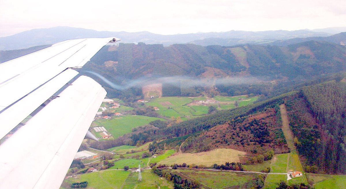
The two streams therefore leave the trailing edge in slightly different directions, shedding a sheet of vorticity that rolls up, a short distance behind the wing, into two concentrated wingtip vortices. Seen from behind the aircraft, the right-tip vortex turns anticlockwise and the left-tip vortex clockwise, so between them the air moves down and outboard of them it moves up. The FAA describes the circulation as outward, upward and around each tip.
The vortices are strongest when the generating aircraft is heavy, clean and slow. Weight sets the lift required; low speed demands a high angle of attack and lift coefficient to produce it, which strengthens the pressure difference across the tip; and in the clean configuration the lift is concentrated into the two tip vortices, whereas extended flaps shed extra, weaker vortices from the flap ends and the turbulence of a dirty configuration hastens the decay of the wake. The FAA AIM states that vortex strength increases in proportion to an increase in weight or a decrease in speed, and that wingspan and wing shape also govern it.
Behind the aircraft the FAA AIM describes the vortices as remaining a little less than a wingspan apart, sinking below the flight path at several hundred feet per minute, weakening with time and distance, and drifting with the wind. Their hazard to other aircraft and the avoidance rules are covered in wake turbulence and jet blast.
Upwash and downwash
Even in two-dimensional flow, a lifting aerofoil disturbs the air around it. Ahead of the leading edge the air is drawn up towards the low pressure above the wing: the upwash. Behind the trailing edge it leaves moving downwards and only gradually returns to its original direction: the downwash. Both are evidence that the wing has done work on the air, turning it downwards to produce lift.
On a real wing the trailing vortices add an induced downwash over the wing itself, on top of the section's own flow pattern. On an untwisted rectangular wing it is strongest near the tips, where the vortices are concentrated.
The downwash behind the wing also reaches the tailplane, which therefore meets air already deflected downwards. More downwash, for example when flap is lowered, increases the tail's download and pitches the nose up; less downwash, as in ground effect, pitches it down.
Induced and effective angle of attack
The geometric angle of attack is the angle between the chord line and the undisturbed relative airflow far ahead of the wing. The induced downwash tilts the local airflow at the wing downwards by a small angle, the induced angle of attack. The wing section actually meets the air at the effective angle of attack, the angle between its chord line and that local airflow:
effective angle of attack = geometric angle of attack − induced angle of attack
Lift acts perpendicular to the local, effective airflow, not to the undisturbed stream, so it is tilted rearwards by the induced angle. Resolved against the undisturbed stream, it has a small rearward component, and that component is induced drag. Stronger vortices mean a larger induced angle, a larger tilt and more induced drag.
The same geometry shapes the lift curve. A finite wing needs a larger geometric angle of attack than its section alone for the same lift, and the more of the span the vortices affect, the flatter its lift curve. A high aspect ratio wing therefore has a steeper lift curve and reaches its stall at a lower angle of attack, with CLmax changed little, while low aspect ratio wings such as deltas stall only at very high angles. The spread of effective angle of attack along the span also decides where the wing stalls first: tip vortices lower the effective angle near the tips of a rectangular wing, so it stalls at the root, whereas the tips of a strongly tapered wing work at a higher local lift coefficient and tend to stall first (see stall).

Induced drag and the factors affecting it
The induced drag coefficient is CDi = CL² ÷ (π × AR), where AR is the aspect ratio, and induced drag itself is CDi × ½ρV² × S. Several practical results follow.
- Speed. At constant weight the lift coefficient required varies with 1/V², so induced drag varies with 1/V²: doubling the speed cuts it to a quarter. It is greatest at low speed and high angle of attack, shortly after lift-off.
- Weight. At a given speed the lift coefficient is proportional to the weight, so induced drag varies with the square of the weight. A 10 % heavier aeroplane has about 21 % more induced drag at the same IAS.
- Load factor. In a level turn the wing must produce the weight multiplied by the load factor, so at the same speed induced drag rises with the square of the load factor: at 60° of bank, where the load factor is 2, it is four times the wings-level value.
- Aspect ratio. At a given lift coefficient, induced drag is inversely proportional to aspect ratio. Typical values are about 3 for a jet fighter, 12 for a jet transport and 35 for a high-performance sailplane.
- Span. Substituting the lift equation gives induced drag = W² ÷ (½ρV² × π × b²), with b the span. For a given weight and speed it is the span, rather than the wing area, that sets the induced drag.
- Altitude. At a constant IAS the dynamic pressure, lift coefficient and induced drag are unchanged. At a constant TAS the air is thinner higher up, the lift coefficient must rise and induced drag increases.
Exam tip: induced drag is reduced by higher speed, lower weight, higher aspect ratio, an elliptical lift distribution and wingtip devices such as winglets and tip tanks. Decreasing the speed at constant altitude increases it. It varies with 1/V², parasite drag with V².
Elliptical lift distribution
How the lift is spread along the span matters as much as its total. For a given span and total lift, induced drag is least when the lift per unit span falls from root to tip along the shape of an ellipse. This elliptical lift distribution produces a uniform downwash across the whole span, so every section works at the same induced angle, and it gives the theoretical minimum induced drag, the value that CL² ÷ (π × AR) describes. Real wings fall short of it by a margin that designers express with an efficiency factor.
An untwisted wing with an elliptical planform produces this distribution, but it is complex to build, and because in theory every section works at the same effective angle of attack it gives no root-first stall to keep the ailerons working. A rectangular wing carries proportionally more load near its tips than the ideal and has more induced drag. Moderate taper moves the distribution towards the ideal at lower structural weight, and washout can refine it while making the root stall first. These choices are covered in wing planform and design.
Winglets and Sharklets
Wingtip devices reduce induced drag without a large increase in span. Tip tanks and end plates limit the spill of air round the tip, although a tip tank adds some parasite drag of its own. Wingtip fences are small surfaces above and below the tip.
A winglet is a near-vertical, usually swept surface rising from the tip. It sits in the rotating inflow of the tip vortex, and the lift it develops in that flow is tilted forwards, giving a small forward force; at the same time it weakens the vortex and the downwash it induces over the wing. Variants include the blended winglet, the split scimitar winglet and the raked wingtip. The saving is greatest where induced drag is high, at high weight and low speed as in the climb, and it adds up on long flights, but the device's weight and the extra bending load on the wing must be repaid by the fuel it saves. The FAA AIM describes the primary function of winglets as improving the lift/drag ratio for fuel efficiency and notes that studies have shown a negligible effect on wake turbulence.
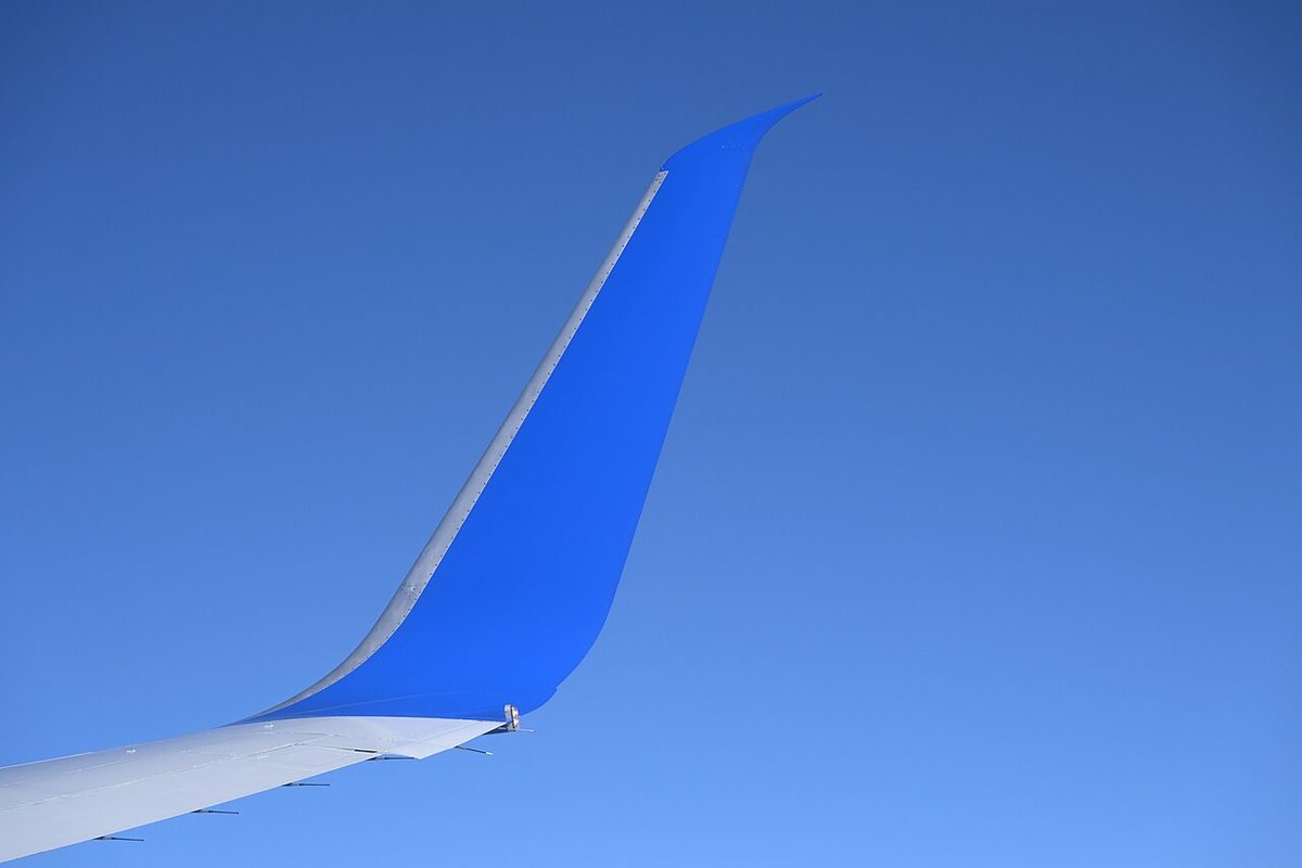
Sharklet is Airbus's name for the large upswept wingtip device of the A320 family, which replaced the small wingtip fences of earlier aircraft. It is standard on the A320neo and is also fitted to some A320ceo aircraft. The A320 flight crew operating manual gives the span as 34.10 m with wingtip fences and 35.80 m with Sharklets.
Ground effect
Ground effect is the change in a wing's behaviour close to the surface. It is felt within about one wingspan of the ground and becomes pronounced below about half a span, so a jet with a 120 ft span begins to feel it at about 120 ft, and a light aeroplane only at a correspondingly lower height. The ground prevents the tip vortices from developing fully and reduces the upwash and downwash. The induced angle falls, the effective angle of attack rises, and the wing produces the same lift at a lower angle of attack with less induced drag. The figures quoted in both FAA and EASA training material for the reduction in induced drag are about 1.4 % at a height of one span, 23.5 % at a quarter of the span and 47.6 % at a tenth. Parasite drag is unchanged. Because the last few metres count most, a low-wing aeroplane feels a stronger ground effect than a high-wing one.
The effects in the cockpit follow:
- Float. With less drag the aeroplane decelerates slowly in the flare, so excess speed turns into runway used. The FAA notes that a 10 % excess in landing speed adds roughly 20 % to the landing distance.
- Pitch. Reduced downwash at the tailplane gives a nose-down pitching moment, so more elevator is needed in the flare. The forward centre of gravity limit is typically set by the elevator authority needed in the flare in ground effect.
- Instruments. In most installations the static pressure at the static source rises slightly, so the altimeter and airspeed indicator read a little low.
- Take-off. An aeroplane can become airborne in ground effect at a speed too low to climb out of it. As it climbs, induced drag rises, a higher angle of attack and more thrust are needed, and it may settle back onto the runway. The soft-field technique is to stay in ground effect and accelerate to a safe climb speed before climbing away.
Near the ground the wake vortices of other aircraft also stop sinking and move outwards across the surface, the behaviour described in wake turbulence and jet blast.
Frequently asked questions
What causes induced drag?
A lifting wing has higher pressure below it than above it, so air flows round the tips from the lower surface to the upper and rolls up into trailing vortices. The vortices induce a downwash over the wing, which tilts the local airflow downwards and the lift vector rearwards by the induced angle of attack. The rearward component of the tilted lift is induced drag. With no lift, there is no induced drag.
Why is induced drag greatest at low speed?
In level flight the wing must produce lift equal to the weight at any speed. At low speed the dynamic pressure is small, so the wing needs a high angle of attack and lift coefficient, which strengthens the tip vortices and the downwash. Induced drag varies inversely with the square of the speed, so halving the speed makes it four times as large. It is therefore greatest just after lift-off and on the approach.
How does aspect ratio affect induced drag?
The induced drag coefficient is CL squared divided by pi times the aspect ratio, so at the same lift coefficient a wing of twice the aspect ratio has half the induced drag. A long, slender wing keeps most of its span away from the influence of the tip vortices. That is why high-performance sailplanes, with aspect ratios of around 35, glide so efficiently, while structural weight limits how far airliners can go.
Do winglets reduce wake turbulence?
Not significantly. Winglets and similar tip devices weaken the tip vortex enough to reduce induced drag and improve the lift/drag ratio, saving fuel, but the FAA AIM states that studies have shown their effect on wake turbulence to be negligible, particularly at the slow speeds of departure and arrival. An aircraft fitted with winglets must be treated as a wake generator like any other of its type and category.
What is ground effect and when does it occur?
Ground effect is the change in a wing's behaviour when it flies within about one wingspan of the surface, becoming pronounced below about half a span. The ground restricts the tip vortices and reduces the downwash, so the effective angle of attack rises and induced drag falls, by nearly half at a tenth of the span. The aeroplane floats in the flare and can lift off before it has the speed to climb away.
Test yourself on Induced Drag and Wingtip Vortices
The v1prep banks cover this topic in Principles of Flight (081), with a worked explanation for every answer. EASA ATPL, PPL, IR and CPL, the FAA written tests and A320/B737 type ratings.
Start practising →Sources and further reading
- FAA Pilot's Handbook of Aeronautical Knowledge (FAA-H-8083-25), Chapter 5, Aerodynamics of Flight
- FAA Aeronautical Information Manual, Chapter 7 Section 4, Wake Turbulence
- FAA Airplane Flying Handbook (FAA-H-8083-3C)
- EASA, Explanatory Note to ED Decision 2018/001/R, Part-FCL theoretical knowledge learning objectives
- NASA Glenn Research Center, Induced Drag Coefficient
- NASA Glenn Research Center, Downwash Effects on Lift
Library articles are written for study and exam preparation. They do not replace your aircraft's approved documentation, your operator's procedures or the regulations themselves.