Propeller Aerodynamics
A propeller is a set of rotating aerofoils, its blades, that produces thrust by accelerating air rearwards. Each blade section meets the air at an angle of attack set by its blade angle and by the combination of the aircraft's forward speed and the section's rotational speed.
A propeller converts the power of an engine into thrust. Each blade is an aerofoil that moves along a helical path, part rotation and part forward motion, and the aerodynamic force it produces is split into a forward component, thrust, and a component in the plane of rotation that resists the engine. How large the thrust is, and how much of the engine's power it represents, depends on the angle at which each blade section meets the air.
That angle is not fixed. It changes with airspeed and rpm, which is why a fixed-pitch propeller is a compromise, why constant-speed propellers exist and why a propeller left turning after an engine failure produces so much drag. The same geometry explains the twist built into every blade, the limits on diameter and rpm, and the forces that try to turn the blades in their hub.
How a propeller produces thrust
A propeller accelerates a mass of air rearwards, and by Newton's third law the air pushes the propeller forward (see Newton's laws and the four forces). The work is done blade section by blade section. Each section meets a relative airflow and, like a wing, produces a total aerodynamic reaction. That reaction is resolved into two components:
- Thrust, perpendicular to the plane of rotation, along the propeller shaft, which drives the aircraft forward.
- Propeller torque, in the plane of rotation and opposed to the rotation, which is the resistance the engine must overcome to keep the propeller turning.
The air driven rearwards forms the slipstream, which spirals round the fuselage behind the propeller. Its effects on the aircraft, together with the reaction to engine torque, are covered in propeller torque and slipstream effects.
Blade angle, helix angle and blade angle of attack
The blade angle (propeller blade angle) is the angle between the chord line of a blade section and the plane of rotation. Because it varies along the blade, the propeller's blade angle is quoted at a reference station, which exam texts place at 75 per cent of the blade length. A small blade angle is called fine pitch, a large one coarse pitch.
A blade section does not meet the air head-on. Its relative airflow is the combination of two velocities: its rotational velocity, which is proportional to rpm and to its distance from the hub, and the aircraft's true airspeed along the axis. The section therefore travels along a helix, and the helix angle is the angle between that helical path, the direction of the relative airflow, and the plane of rotation. The propeller blade angle of attack is the angle between the chord line and the relative airflow:
blade angle of attack = blade angle − helix angle
The blade angle is set by the hub; the helix angle is set by the flight condition. For a fixed blade angle:
| Change | Helix angle | Blade angle of attack | Effect |
|---|---|---|---|
| TAS increases, rpm constant | Increases | Decreases | Less thrust and less torque absorbed |
| rpm increases, TAS constant | Decreases | Increases | More thrust, until the blade nears its stall |
| Aircraft stationary | Zero | Equal to the blade angle | Large angle of attack, high torque |
| Very high TAS | Approaches the blade angle | Approaches zero | Thrust falls to zero |
The table explains a familiar sight in a fixed-pitch trainer. At the start of the take-off roll the blades work at a large angle of attack and absorb so much torque that the engine cannot reach its maximum rpm at full throttle; as the aircraft accelerates, the angle of attack falls, the load comes off and the rpm rises.
Blade twist
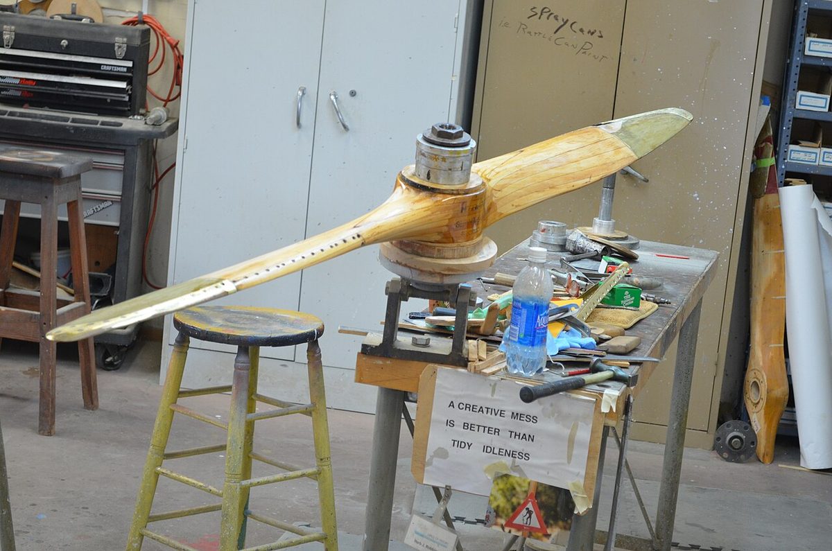
Every section of a blade shares the same forward speed, but the tip travels a much longer path in each revolution than a section near the hub, so its rotational velocity is higher and its helix angle smaller. If the blade angle were the same all along the blade, the root would work at a very high angle of attack, close to the stall, while the tip met the air almost edge-on and produced little thrust.
Propeller blade twist solves this. The blade angle is made largest at the root and smallest at the tip, so that each section works near its most efficient angle of attack and the thrust is spread reasonably evenly along the blade. Looking along a propeller from the tip, the twist is plain to see.
Geometric pitch, effective pitch and slip
Propeller geometry is also described by distances. The geometric pitch is the distance the propeller would advance in one revolution if it moved like a screw through a solid, following its blade angle exactly. The effective pitch is the distance it actually advances through the air in one revolution, the aircraft's true airspeed divided by the revolutions per unit time. Propeller slip is the difference:
slip = geometric pitch − effective pitch
Slip exists because air is a fluid: the propeller gives it a rearward velocity instead of screwing through it. Slip is not simply a loss. It is the reason the blade meets the air at a positive angle of attack, so a propeller producing thrust always has slip; a propeller advancing its full geometric pitch would produce little or no thrust.
In everyday use "pitch" often means blade angle, as in fine and coarse pitch. The two ideas are the same geometry seen two ways: a larger blade angle gives a larger geometric pitch.
Fixed and variable pitch
A fixed-pitch propeller has one blade angle, so it works at its best angle of attack at only one combination of airspeed and rpm. Away from that point its efficiency falls. Manufacturers may offer a climb propeller with a lower pitch, which lets the engine turn faster and develop more power at low airspeed for take-off and climb, and a cruise propeller with a higher pitch, which is more efficient at high speed but limits rpm and power at low speed.
A variable-pitch propeller removes the compromise by changing blade angle in flight. On a controllable-pitch propeller the pilot sets the blade angle. On a constant-speed propeller the pilot selects an rpm and a governor, or constant speed unit, varies the blade angle to hold it:
- On the take-off roll, at low TAS and maximum rpm, the relative airflow comes mostly from the rotation, so the governor sets a fine pitch.
- As TAS rises the helix angle grows, the blade angle of attack and torque fall, and the propeller starts to overspeed; the governor coarsens the blades to restore the selected rpm.
- If the aircraft slows in a climb, the propeller starts to slow and the governor fines the blades.
The blades therefore stay near their best angle of attack across a wide speed range. The governor, feathering and reverse pitch are described in propellers and propeller control.
Efficiency, shaft power and thrust power
The engine delivers shaft power, its torque multiplied by the angular velocity of the shaft. FAA material calls it brake horsepower (BHP). The propeller turns it into thrust power, thrust multiplied by true airspeed, which FAA texts call thrust horsepower (THP). Propeller efficiency is the ratio of the two:
propeller efficiency = thrust power ÷ shaft power
The losses come chiefly from the profile drag of the blades, from tip losses and from the swirl left in the slipstream. A well-matched constant-speed propeller peaks at roughly 85 per cent; the FAA's Pilot's Handbook gives about 50 to 87 per cent for typical light aeroplane propellers.
Efficiency varies strongly with airspeed. At the start of the take-off roll TAS is zero, so thrust power, and with it efficiency, is zero even though thrust is at its greatest. As speed builds, efficiency rises to a peak. On a fixed-pitch propeller it then falls again as the blade angle of attack tends to zero at high TAS. A variable-pitch propeller holds it near its peak over a much wider range, which is why the power available from a propeller aeroplane rises with speed through the climb range (see power curves and speed stability).
Exam tip: efficiency = thrust × TAS ÷ shaft power. It is zero when stationary, however much thrust the propeller makes, and a fixed-pitch propeller is efficient at only one combination of airspeed and rpm.
Tip speed and solidity
The tip of a blade moves faster than any other part of the propeller. Its helical tip speed, or propeller tip speed, is the combination of its rotational speed and the aircraft's true airspeed. As it approaches the local speed of sound, shock waves form near the tips: thrust falls, drag rises and noise rises sharply. This sets the practical limit on the combination of diameter, rpm and airspeed. A fast aeroplane reaches the critical tip Mach number at a lower rpm than a slow one, which is one reason faster piston aeroplanes use reduction gearing to turn the propeller slower than the engine.
A more powerful engine needs a propeller that can absorb more power, but a larger diameter would raise the tip speed. The answer is to increase the propeller solidity, the ratio of the total blade area to the area of the propeller disc. Solidity can be raised with wider blades, which lowers their aspect ratio, or with more blades, which is usually preferred. For very high powers, two propellers turning in opposite directions on the same axis, contra-rotating propellers, raise solidity further and also cancel the torque reaction.
Centrifugal twisting moment
A spinning blade carries forces that try to twist it about its pitch-change axis, the axis about which the hub turns it to change blade angle:
- Centrifugal twisting moment (CTM). The centrifugal force acting on the blade's mass produces a moment about the pitch-change axis that tends to turn the blade towards fine pitch. In normal operation it is the dominant twisting moment.
- Aerodynamic twisting moment (ATM). The centre of pressure of the blade lies ahead of the pitch-change axis, so the aerodynamic force tends to turn the blade towards coarse pitch, partly offsetting the CTM. When the propeller is windmilling the aerodynamic force reverses, and the ATM then acts towards fine pitch, reinforcing the CTM.
Designers use these moments. Most single-engine constant-speed propellers use oil pressure to increase blade angle and rely on the centrifugal twisting moment and springs to return the blades to fine pitch, so a loss of oil pressure sends the blades fine and the engine tends to overspeed. Feathering propellers on twins are arranged the other way: oil pressure holds the blades fine, and springs or compressed nitrogen drive them towards feather, so a loss of oil pressure feathers the propeller rather than leaving it windmilling.
Windmilling
A windmilling propeller is one driven round by the airflow instead of by its engine. When an engine fails, the propeller slows, the helix angle grows beyond the blade angle and the blade angle of attack becomes negative. The aerodynamic force now tilts so that it drives the propeller round while its rearward component, drag, becomes large. The propeller is extracting energy from the airstream to turn the dead engine, and the aeroplane pays for it in drag.
A constant-speed unit makes this worse. It sees the falling rpm as an underspeed and does what it always does: it fines the blades to restore the selected rpm. A propeller windmilling in fine pitch gives the greatest drag of any condition. In descending order, the drag of an inoperative propeller is:
- Windmilling, particularly in fine pitch, the greatest.
- Stopped but not feathered, with the blades flat to the airflow: less, since there is drag but no torque.
- Feathered, the least: the blades are turned to about 90°, edge-on to the airflow, the rotation stops and no torque is produced.
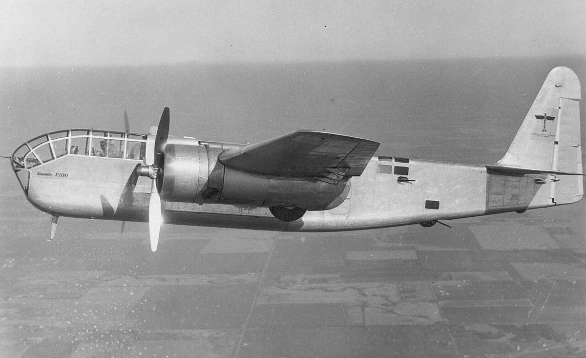
On a twin the drag of a windmilling propeller adds to the yaw towards the failed engine, raises the minimum control speed and eats most of the remaining climb performance, which is why prompt identification and feathering is central to asymmetric flight. A single-engine aeroplane with a constant-speed propeller but no feathering can reduce windmilling drag after an engine failure by pulling the propeller control to fully coarse. The blade angle of attack is then less negative, rpm falls, drag decreases and the glide improves, subject always to the pilot's operating handbook.

Frequently asked questions
What is the difference between blade angle and blade angle of attack?
Blade angle is the angle between the chord line of a blade section and the plane of rotation. It is fixed by the hub setting and the blade's twist. Blade angle of attack is the angle between the chord line and the relative airflow the section actually meets, which comes from the combination of rotational speed and forward speed. The angle of attack equals the blade angle minus the helix angle, so it changes with airspeed and rpm.
Why is a propeller blade twisted?
Every section of a blade has the same forward speed, but its rotational speed increases with its distance from the hub, so the relative airflow meets the outer sections at a flatter angle. To keep a roughly constant angle of attack along the whole blade, the blade angle is made largest at the root and smallest at the tip. Without twist the root would work near the stall while the tip produced little thrust.
What is propeller slip?
Slip is the difference between geometric pitch, the distance a propeller would advance in one revolution if it moved like a screw through a solid, and effective pitch, the distance it actually advances. Slip exists because the propeller works on a fluid, giving the air a rearward velocity. It is what gives the blades their angle of attack, so a propeller that produces thrust always has some slip.
How is propeller efficiency defined?
Propeller efficiency is thrust power divided by shaft power: the thrust multiplied by the true airspeed, divided by the power the engine delivers to the propeller shaft. FAA material expresses the same ratio as thrust horsepower over brake horsepower. A well-matched propeller peaks at roughly 85 per cent. At the start of the take-off roll the airspeed is zero, so thrust power and efficiency are zero however much thrust is produced.
Why does a windmilling propeller produce so much drag?
When the engine stops delivering power, the airflow drives the propeller round. The blades meet the air at a negative angle of attack, and the aerodynamic force tilts rearwards, producing drag while it turns the dead engine. A constant-speed unit makes matters worse by driving the blades to fine pitch in an attempt to hold the selected rpm. Feathering turns the blades edge-on, stops the rotation and removes most of the drag.
Test yourself on Propeller Aerodynamics
The v1prep banks cover this topic in Principles of Flight (081), with a worked explanation for every answer. EASA ATPL, PPL, IR and CPL, the FAA written tests and A320/B737 type ratings.
Start practising →Sources and further reading
Library articles are written for study and exam preparation. They do not replace your aircraft's approved documentation, your operator's procedures or the regulations themselves.