Wheel Brakes
Aircraft wheel brakes are friction brakes in the main wheels that turn the aircraft's kinetic energy into heat. Transport aircraft use hydraulically operated multi-disc steel or carbon brakes, with normal, alternate and parking functions, wear indicators and protection against overheating.
Wheel brakes stop an aircraft by friction between fixed and rotating surfaces, turning its kinetic energy into heat. Reverse thrust and spoilers help, but on a dry runway the wheel brakes do most of the work, and the rejected take-off at high speed and high mass is the stop for which they are sized.
That heat is the central problem of brake design. Brakes must absorb it without failing, store it safely while it slowly leaks away, and stay controllable when the hydraulic system that operates them has failed. This article covers how brakes are built and operated; the energy limits they place on take-off and landing are covered in brake energy and tyre speed limits, and automatic brake modulation in anti-skid and autobrake.
Multi-disc brake construction
Essentially all modern aircraft use disc (plate) brakes operated by hydraulic pressure. A light aircraft typically has a single disc on each main wheel, squeezed by a caliper; each toe brake works its own master cylinder, so the left and right brakes are independent. Transport aircraft use the multi-disc brake, which multiplies the friction surfaces to absorb far more energy in the same wheel.
In a multi-disc brake, rotors are keyed to the wheel and turn with it. Stators are keyed to a torque tube on the brake housing, which is mounted on the axle and does not turn. Rotors and stators alternate in a stack between a pressure plate at the piston end and a thrust plate, or back plate, at the other. When the pilot brakes, hydraulic pistons in the housing push the pressure plate and clamp the whole stack together. The main wheels carry the brakes; on the Boeing 737, for example, each main wheel has a multi-disc brake and the nose wheels have none.
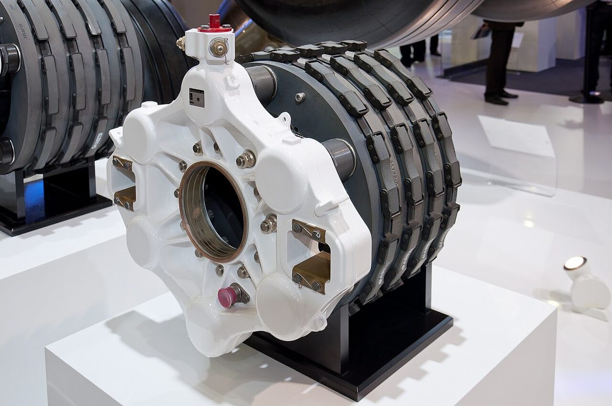
Carbon and steel brakes
In a steel brake the stators carry pads of friction material and the rotors are heavy steel discs with a case-hardened surface. Steel brakes are cheaper, but heavy.
Carbon brakes use discs of carbon-carbon composite. They are much lighter than steel units and absorb and dissipate heat better, at a higher purchase cost. They are found on long-haul types and on short-haul ones such as the A320 family, whose main wheels have carbon multi-disc brakes.
Carbon brakes behave differently in service:
- Wear depends mainly on the number of brake applications and on brake temperature, not on the pressure or duration of each application. The way to reduce wear is fewer applications. Airbus suggests that on a long straight taxiway the A320 be allowed to accelerate to 30 kt and then slowed to 10 kt with one smooth application, rather than braked continuously.
- Oxidation is the other limit on their life. It is caused mainly by repeated high brake temperatures, particularly above 400 °C, and can weaken a disc until it breaks. Airbus therefore recommends autobrake LO for landing when performance permits.
Brake control and metering valves
The pilot's pedals do not apply system pressure directly to the brakes. They operate brake metering valves (Boeing's term) or a brake control valve, which European training texts describe as a variable pressure-reducing valve: its output pressure follows the pedal deflection, is reduced by the anti-skid system when a wheel starts to skid, and is set by the autobrake when that is in use. A modulator valve may give full flow on the first application, for a quick response, and restricted flow afterwards so that the anti-skid can modulate the pressure smoothly.
On newer aircraft the pedals are electrical transmitters. The A320's pedals send their signals to the brake and steering control unit (BSCU), which commands servo valves; the E190-E2 brakes are brake-by-wire, electrically commanded and hydraulically actuated.
Some systems also have brake torque limiting. A torque sensor at each wheel detects excessive braking torque, which could overload the gear structure, and releases the pressure to that brake. Training texts note it matters particularly with carbon brakes, which can develop very high peak torque.
Normal, alternate and parking brakes
Brakes are too important to depend on one hydraulic system. Transport aircraft have a normal brake system on one hydraulic system, an alternate brake system on another that takes over automatically when normal pressure is lost, and a brake accumulator that stores enough pressure for a limited number of applications and for the parking brake when the pumps are not running.
| Normal | Alternate | Back-up | |
|---|---|---|---|
| Boeing 737 NG | System B | System A, automatic if B is low or fails | Accumulator charged by system B: several applications or the parking brake |
| Airbus A320 | Green, through the BSCU | Yellow, through the ABCU | Yellow accumulator: at least 7 full applications |
| Embraer E190-E2 | Brake-by-wire: system 1 outboard brakes, system 2 inboard brakes | None as such: each system brakes its own pair of wheels | Emergency/parking brake on two accumulators: 6 full applications or 12 h of parking |
Anti-skid usually remains in alternate braking, sometimes in a simpler form, but the autobrake works only with the normal system. On the A320, brake pressure is shown on a triple indicator only when the yellow system supplies the brakes, in alternate braking or with the parking brake set; in alternate braking without anti-skid the pressure is limited to 1,000 psi to avoid locking the wheels.

The parking brake traps pressure in the brakes. In the classic design the pilot presses the pedals, sets the parking brake lever, which closes a valve in the return line, and releases the pedals. On the 737 the pedals are pressed fully while the PARKING BRAKE handle is pulled up, which latches them, and a red light shows the brake is set. On the A320 the PARK BRK handle is pulled and turned to ON, and the accumulator holds the pressure for at least 12 hours. Neither relieves the crew of judgement: Boeing warns not to assume that the parking brake can prevent movement, since accumulator pressure may be insufficient, and Airbus states that the A320's brakes are not designed to hold the aircraft stationary with high thrust on an engine. A parking brake left set also triggers the take-off configuration warning when take-off thrust is applied.
One automatic application happens in flight. When the gear is selected up, the main wheels are braked so that they stop spinning before entering the wheel wells: on the A320 the normal brake system does this, and on the 737 the brakes stop the main wheels during retraction. Braking before touchdown, by contrast, is not approved on the 737 because it damages tyres and gear, and the anti-skid touchdown protection is designed to prevent it.
Differential braking
The left and right brakes are controlled separately, through the left and right pedals. Differential braking, braking one side harder than the other, is a steering tool: it turns an aircraft with a castoring nose wheel, tightens a turn, and steers the aircraft when nose wheel steering has failed. On the A320 it remains available through the pedals even with the A/SKID & N/W STRG switch OFF. Anti-skid is switched off at very low speed partly so that a wheel can be held stationary for a tight turn: the E190-E2's is disabled below 10 kt to allow pivoting on a wheel.
One advantage of powered nose wheel steering is that routine turns need no differential braking, which saves brakes and tyres (see nose wheel steering).
Brake wear and adjusters
As the friction material wears, the pistons would have to travel further each time. A brake adjuster assembly prevents this: when pressure is released, return springs pull the pressure plate back by a fixed amount, so the brake keeps a constant running clearance whatever its wear.
Wear is checked with brake wear indicator pins, also called brake wear pins, which protrude from the brake housing. With the brakes applied, the length of pin still standing out shows the wear material left; on the Boeing 737 walk-round, with the parking brake set, the pins must extend out of their guides, and the A320 walk-round checks the pin length the same way. Without pins, the clearance between the back of the pressure plate and the brake housing is measured with the brakes applied. Excessive wear is dangerous because the remaining material overheats and erodes rapidly. For certification, the maximum brake energy rejected take-off is demonstrated with not more than 10 per cent of the allowable wear range remaining.
Brake temperature monitoring
Large aircraft have a brake temperature indication system, with a sensor in each brake. On the A320 WHEEL page each brake temperature is shown in green; an arc appears over the hottest when one exceeds 100 °C, turning amber with an ECAM caution above 300 °C, the take-off limit with the brake fans off. On the E190-E2 the BRK OVERHEAT message appears above 420 °C. Such systems also expose a single faulty brake: a dragging brake, one hotter than its neighbours, shows before it does harm, and Airbus calls for maintenance action when temperatures within a gear or between the two gears differ by set amounts.
Brake cooling fans, optional on the A320, blow air through the brakes to cool them quickly after landing or before a quick turnaround. They make the indication read low, by about 50 °C at an actual 100 °C and about 150 °C at an actual 300 °C, so with the fans running take-off is delayed while any indicated temperature is above 150 °C. They are not run during take-off, to avoid foreign object damage to the fans and brakes.
Brake fade and dragging brakes
Brake fade is the loss of braking effect when a brake is too hot. As the discs and linings heat up, their friction coefficient falls, so the same pedal pressure gives less retarding force, while the pedal itself feels normal. It follows repeated heavy braking or a high-energy stop, and the only cure is cooling time. In a light aircraft, a soft, spongy pedal is a different symptom: hydraulic fluid boiling near an overheated brake.
Brake drag is a brake that does not fully release, usually because the return spring in the adjuster has stopped working or the brake has been wrongly adjusted. It keeps generating heat while the aircraft rolls, so that the brake starts the next stop already hot and close to fade, and it can damage the wheel and tyre.
Hot brakes and wheel fires
After a heavy stop the brakes keep heating up after the aircraft has stopped: training texts say brake packs can reach their peak temperature up to 30 minutes after the application. The heat soaks into the wheel, whose aluminium alloy weakens, and into the tyre. Fuse plugs in the wheel melt at a set temperature and let the tyre deflate rather than burst (see aircraft wheels and tyres).
The precautions follow from this:
- Do not set the parking brake unless it is essential. It clamps the hot discs together and drives more heat into the wheel. Chocks hold the aircraft instead. Airbus recommends releasing the A320 parking brake once chocks are in place if any brake is above 300 °C, or 150 °C with the fans running.
- Approach hot wheels from the front or rear, never from the side. Fuse plugs, tyres and wheels fail sideways, along the line of the axle.
- Keep the fire service informed, and if an aircraft with hot brakes has to taxi, a fire vehicle follows it in radio contact.
- Allow the cooling time given by the brake cooling schedule before the next take-off.
A wheel and brake fire is fought with dry powder. Water or foam on red-hot case-hardened steel brake plates can make them shatter violently, and magnesium alloy wheels react violently with water. On the 737 the main wheel wells have fire detection but no extinguishing system; the procedure is to extend the gear so that the airflow cools the wheel well.
Warning: the brake cooling schedule assumes a stop that ended normally. A tyre that has deflated, a smell of burning or smoke from the gear after a high-energy stop means the fire service, not the next departure, comes first.
Frequently asked questions
Why do airliners use carbon brakes?
Carbon brakes are much lighter than steel brakes and absorb and dissipate heat better, which suits the high-energy stops of transport aircraft. They cost more, and their wear depends mainly on the number of brake applications rather than on how hard each one is. Pilots therefore taxi with a few firm applications, releasing fully in between, rather than riding or dabbing the brakes.
What is brake fade?
Brake fade is the loss of braking effect when brakes become too hot. As the temperature of the discs and linings rises, their friction coefficient falls, so the same pedal pressure produces less retarding force. It follows repeated heavy braking or a high-energy stop. The only cure is cooling time before the next heavy application. A soft, spongy pedal instead points to hydraulic fluid boiling in an overheated light aircraft brake.
Why should the parking brake not be set on hot brakes?
Setting the parking brake clamps the hot discs together and holds the heat in the brake, so more of it soaks into the wheel and tyre, raising the risk of a melted fuse plug or a damaged wheel. After a heavy stop the aircraft is held with chocks instead. Airbus, for example, recommends releasing the A320 parking brake once chocks are in place if any brake is above 300 °C.
How is brake wear checked on an airliner?
Most multi-disc brakes have wear indicator pins that protrude from the brake housing. With the brakes applied, normally by setting the parking brake, the length of pin still standing out shows how much wear material remains; on the Boeing 737 the pins must extend out of their guides. Without pins, the clearance between the pressure plate and the brake housing is measured with the brakes applied.
How is a wheel brake fire fought?
With dry powder, approaching from the front or rear of the wheel, never from the side. Water or foam on red-hot case-hardened steel brake plates can make them shatter violently, and magnesium wheels react violently with water. Fuse plugs, tyres and wheels release their energy sideways along the line of the axle, which is why anyone near hot wheels stays ahead of or behind them.
Test yourself on Wheel Brakes
The v1prep banks cover this topic in Aircraft General Knowledge (021), with a worked explanation for every answer. EASA ATPL, PPL, IR and CPL, the FAA written tests and A320/B737 type ratings.
Start practising →Sources and further reading
- FAA Aviation Maintenance Technician Handbook, Airframe (FAA-H-8083-31B), Chapter 13, Aircraft Landing Gear Systems
- 14 CFR 25.735, Brakes and braking systems
- 14 CFR 25.109, Accelerate-stop distance
- EASA Easy Access Rules for Large Aeroplanes (CS-25), CS 25.735 Brakes and braking systems
- EASA Easy Access Rules for Aircrew (Part-FCL), theoretical knowledge syllabus, 021 Airframe, Systems, Electrics, Power Plant
- FAA AC 120-62, Takeoff Safety Training Aid
Library articles are written for study and exam preparation. They do not replace your aircraft's approved documentation, your operator's procedures or the regulations themselves.