Hydraulic Valves and Actuators
Hydraulic valves control where the fluid in an aircraft hydraulic system may flow, in which direction, in what order and at what pressure. Hydraulic actuators, the jacks and motors, convert that pressurised flow into the linear or rotary movement that operates gear, flaps, brakes and flight controls.
Once a pump has made pressure, the rest of a hydraulic system decides what the pressure does. Valves determine where the fluid may go, in which direction, in what order and at what pressure. Actuators, the jacks and hydraulic motors, turn the pressurised flow into the linear or rotary movement that raises the gear, sets the flaps, applies the brakes and deflects the control surfaces.
Most valves fall into three families: those that direct flow (selector, non-return, shuttle and sequence valves), those that control its rate (restrictors and modulators), and those that limit or cut pressure (relief, priority and reducing valves). How the pressure is made is covered in hydraulic pumps and power sources.
Selector and spool valves
A selector valve sends fluid to the chosen side of an actuator and connects the other side to the return line, giving positions such as up and down, extend and retract, or open and close. On small aircraft it is moved by hand; on transport aircraft it is operated remotely, mechanically or electrically. Selector valves are built as open-centre or closed-centre valves to suit the system.
There are two constructions. A rotary selector turns a spool or disc to line up ports: two ports serve a single-acting actuator, four a double-acting one. A spool valve (linear slide valve) moves a spool with raised lands along its bore, opening and closing ports as it slides; it is worked by a rod or cable, or electrically by a solenoid.
An electrohydraulic valve is a hydraulic valve opened or closed by an electrical signal, usually through a solenoid. Examples on the A320 are the two PTU valves, open when the PTU switch is in AUTO and closed when it is OFF, and the leak measurement valves, which shut off supply to the primary flight controls when selected from the maintenance panel. The blocking valve in a 737 engine-driven pump is another.
Check valves and restrictors
A non-return valve (NRV), also called a check valve, allows full flow in one direction and blocks flow in the other, like an electrical diode. It is usually a ball or poppet held on its seat by a spring, with an arrow on the casing showing the permitted flow. Non-return valves prevent backflow, keep accumulators charged and isolate parts of the system. On the 737 a check valve in each pump output line isolates that pump from the system, and a non-return valve downstream of an automatic cut-out valve holds system pressure while the pump is off-loaded.
A one-way restrictor valve (choke) gives restricted flow one way and full flow the other, so it slows an actuator in one direction only. The restriction is usually fixed. Typical uses are limiting the speed of flap retraction and slowing landing gear extension so that the gear does not slam down.
Relief and thermal relief valves
A relief valve is a safety device that opens at a set pressure above normal and returns fluid to the reservoir, so that pipes and components are not damaged by overpressure. The system relief valve is one of the six basic components of every hydraulic system.
- A full-flow relief valve, or high-pressure relief valve, sits downstream of the pump and is sized to pass the whole pump output. It opens if the automatic cut-out valve fails to off-load the pump or a blockage stops the normal flow. It is the last line of defence and should never operate in normal use.
- A thermal relief valve protects sections isolated by a non-return valve or selector. If the trapped fluid warms and expands, its pressure rises quickly; the valve opens slightly above normal system pressure, about 10 % higher, and bleeds a little fluid back to the reservoir.
- A flap relief valve protects the flaps against excessive air loads. If they are lowered at too high an airspeed, above VFE, it lets fluid bypass the flap actuator so the flaps blow back towards up until the load falls.

Priority, reducing, sequence and shuttle valves
A priority valve, or pressure maintaining valve, protects the primary services when pressure is degraded, for example on one pump or with a leak. As system pressure falls it closes off the secondary services first. On the A320, priority valves cut off heavy-load users when a system's pressure is low, keeping pressure for the primary flight controls; on the E190-E2, the priority valve isolates the landing gear and nose wheel steering so the flight controls get priority.
A pressure reducing valve supplies one service at less than system pressure, typically the wheel brakes. It senses the pressure downstream and closes as that pressure reaches the set value. The brake control valve is a variable reducing valve driven by the brake pedals, the anti-skid system and the autobrake, and a modulator valve gives full flow on the first brake application, then restricted flow so that anti-skid can modulate pressure smoothly.
A sequence valve makes actuators work in the right order. It feeds one actuator only until that actuator reaches a set position or pressure, then opens the way to the next. The classic case is the landing gear: the doors must open before the gear extends, and close only after it has retracted.
A shuttle valve lets one service run from either a normal or an alternate supply and changes over automatically. Normal pressure holds the shuttle over the alternate port; if normal pressure is lost, alternate pressure pushes the shuttle across, blocks the normal line and feeds the service. Shuttle valves are common in landing gear and brake systems.
| Valve | What it does | Typical use |
|---|---|---|
| Selector | Directs fluid to one side of an actuator | Gear, flaps, doors |
| Non-return (check) | Flow one way only | Pump outlets, accumulators |
| One-way restrictor | Slows flow in one direction | Flap retraction, gear extension |
| Thermal relief | Relieves trapped fluid as it expands | Isolated lines and jacks |
| Priority | Sheds secondary services at low pressure | Protects flight controls |
| Sequence | Makes actuators work in order | Gear doors and gear |
| Shuttle | Changes to the alternate supply | Gear and brakes |
Hydraulic lock
A hydraulic lock exists when fluid is trapped between an actuator piston and a closed non-return valve or selector. The fluid cannot flow out, and because it is practically incompressible, the piston cannot move even under a large load. Designers use this deliberately: a selector left at an intermediate position holds the flaps where they are, and the landing gear can be held up hydraulically before its uplock engages. In a powered flying control unit, the control valve returns to neutral when the surface reaches the commanded position and covers both actuator ports, trapping fluid on both sides of the piston. The surface is then locked against air loads, which is why such a system is irreversible and needs artificial feel.
A lock can also be unwanted. Where two power control units on separate hydraulic systems drive one surface, a unit that loses pressure opens a spring-loaded bypass that connects both sides of its piston, so that it follows the working unit instead of locking the surface. Hydraulic power alone does not always hold a surface, either: leading edge devices driven by hydraulic motors and screw jacks may back-drive under air load when hydraulic power is removed, so they can need mechanical locks.
Linear actuators and jacks
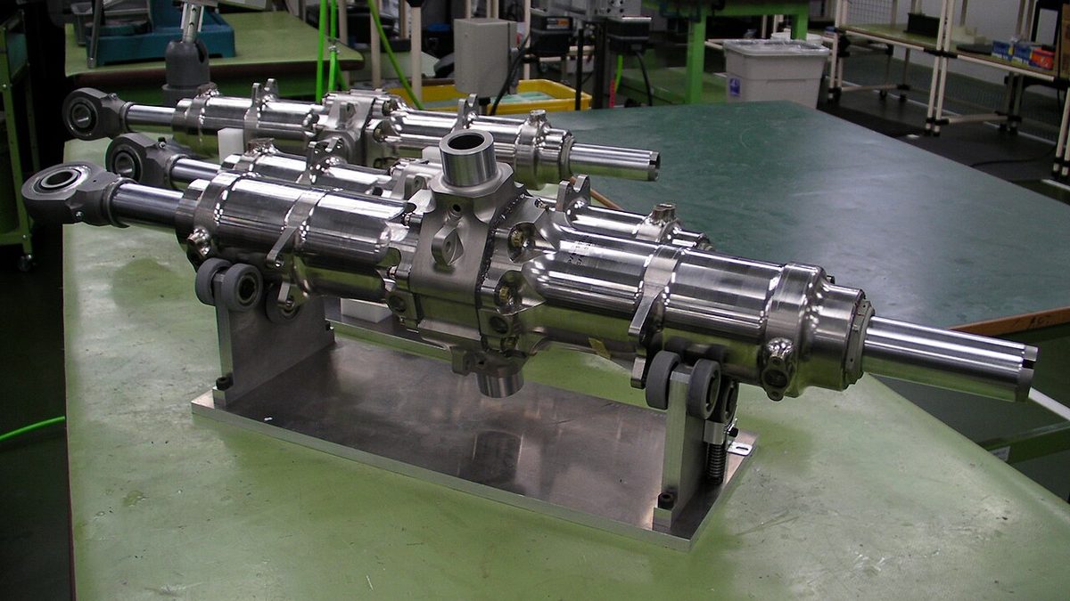
A hydraulic actuator (jack) is a cylinder containing a piston with seals, whose rod leaves through a gland seal at one end. Its force is pressure times the effective piston area.
- A single-acting jack is driven by pressure in one direction only and returned by a spring. The classic use is the landing gear downlock: the spring holds the lock engaged, which is the fail-safe state, and pressure is needed only to release it.
- A double-acting unbalanced jack, the most common type, can be pressurised on either side. The rod occupies part of the piston area on its side, so extension gives more force than retraction, and the designer puts the harder task, such as gear retraction against the airflow, on the full-area side.
- A double-acting balanced jack has a rod through both ends, equal areas and so equal force in both directions. It suits nose wheel steering and flying control boost units.
For example, at 3,000 psi a piston of 5 in² with a 1 in² rod pushes with 15,000 lb when extending but pulls with only 12,000 lb when retracting, because only 4 in² is left on the rod side.
Hydraulic motors
A hydraulic motor is a rotary actuator. It is built much like a multi-piston variable-volume pump run in reverse, and its speed depends on the rate of flow entering it. On the A320, two hydraulic motors drive the screwjack of the trimmable horizontal stabiliser; the flap and slat power control units each have two hydraulic motors coupled through a differential gearbox, using green and blue power for the slats and green and yellow for the flaps; and the blue system drives the emergency generator through a hydraulic motor. The motor half of a power transfer unit is another example.
Servo valves and torque motors
In a powered flying control the pilot's linkage moves a control valve rather than the surface. The valve admits pressure to one side of the actuator and opens the other to return; as the actuator moves, a follow-up linkage moves the valve back towards neutral, and flow stops when the surface reaches the commanded position. Deflection is therefore proportional to the input, without which the surface would simply run to its stop.
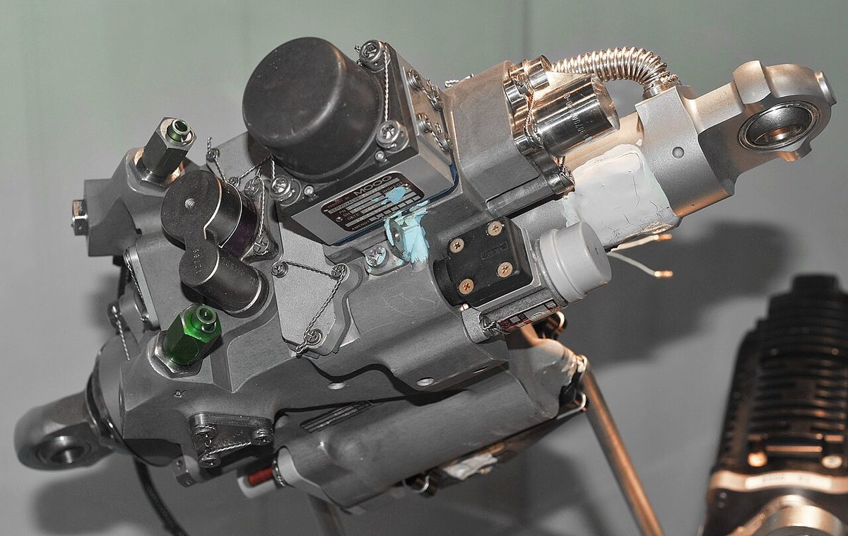
A servo valve is a valve that meters flow to an actuator in proportion to a small input. In a fly-by-wire aircraft the flight control computer sends an electrical signal to a servo valve on each actuator; the surfaces are still moved hydraulically on types such as the A320. An anti-skid system also uses a servo valve to modulate brake pressure.
A torque motor is the electrical input stage of such an electrohydraulic servo valve: it converts an electrical command into a small, precise movement that positions the hydraulic valve. Torque motors are not limited to flight controls: in the hydromechanical unit (HMU) of an A320 engine, the FADEC positions the fuel metering valve through a torque motor and servo valve.
Electro-hydrostatic and electrical backup actuators
An electro-hydrostatic actuator (EHA), which exam texts also expand as electro-hydraulic or electrically powered hydraulic actuator, is self-contained. An electric motor drives a small pump inside the actuator, which moves the piston, so electrical power is the only input and no central hydraulic system is needed. An electrical backup hydraulic actuator (EBHA) normally works from a central hydraulic system like a conventional actuator, but switches to its own electric motor and pump if that system fails.
Airbus uses both on the A380 and A350, alongside conventional hydraulic actuators. They reduce dependence on the central hydraulic systems and add further redundancy, at the cost of more weight than a purely hydraulic actuator.
Exam tip: hydraulic lock needs fluid trapped by a closed NRV or selector; a thermal relief valve protects it. An unbalanced jack is stronger extending than retracting; a balanced jack is equal both ways. A shuttle valve changes supply automatically; a sequence valve sets the order.
Frequently asked questions
What is a hydraulic lock?
A hydraulic lock exists when fluid is trapped on one or both sides of an actuator piston, typically by a closed non-return valve or a selector valve in its neutral position. Because the fluid is practically incompressible, the piston cannot move even under a large load. Designers use it deliberately to hold flaps at an intermediate setting or a flight control surface in position, and thermal relief valves protect such trapped fluid from overpressure when it warms.
What does a priority valve do in a hydraulic system?
A priority valve, also called a pressure maintaining valve, protects the most important services when system pressure falls. It closes off secondary services first, such as landing gear or other heavy users, so that the flight controls keep enough pressure. On the A320 priority valves cut off heavy-load users when pressure is low, and on the E190-E2 the priority valve isolates the landing gear and nose wheel steering in favour of the flight controls.
What is the difference between a balanced and an unbalanced hydraulic jack?
In a double-acting unbalanced jack the piston rod leaves from one side only, so the rod takes up part of the piston area on that side. Extension, with pressure on the full area, gives more force than retraction, and the designer puts the harder task on the full-area side. In a balanced jack the rod passes through both ends, the two areas are equal, and the force is the same in both directions, as needed for nose wheel steering.
What is a shuttle valve used for?
A shuttle valve lets one service be operated from either a normal or an alternate hydraulic supply without any action by the crew. Normally, pressure from the normal supply holds the shuttle against the alternate port. If normal pressure is lost, pressure from the alternate supply pushes the shuttle across, blocking the normal line and feeding the service from the alternate source. Shuttle valves are common in landing gear and brake systems.
What is the difference between an EHA and an EBHA?
An electro-hydrostatic actuator (EHA) needs only electrical power: an electric motor drives a small pump inside the actuator, which moves its piston, so it has no connection to a central hydraulic system. An electrical backup hydraulic actuator (EBHA) normally works from a central hydraulic system like a conventional actuator, but switches to its own electric motor and pump if that system fails. Airbus uses both on the A380 and A350.
What does a thermal relief valve do?
A thermal relief valve protects a section of pipe or an actuator that has been isolated by a non-return valve or selector. If the trapped fluid warms, for example on the ground in the sun, it expands and its pressure rises quickly because it has nowhere to go. The thermal relief valve opens at a pressure slightly above normal system pressure, typically about 10 % higher, and bleeds a little fluid back to the reservoir before anything is damaged.
Test yourself on Hydraulic Valves and Actuators
The v1prep banks cover this topic in Aircraft General Knowledge (021), with a worked explanation for every answer. EASA ATPL, PPL, IR and CPL, the FAA written tests and A320/B737 type ratings.
Start practising →Sources and further reading
- FAA Aviation Maintenance Technician Handbook, Airframe (FAA-H-8083-31), Hydraulic and Pneumatic Power Systems
- EASA Easy Access Rules for Aircrew (Part-FCL), theoretical knowledge syllabus, 021 Airframe, Systems, Electrics, Power Plant
- EASA Easy Access Rules for Large Aeroplanes (CS-25), CS 25.1435 Hydraulic systems
- 14 CFR 25.1435, Hydraulic systems
Library articles are written for study and exam preparation. They do not replace your aircraft's approved documentation, your operator's procedures or the regulations themselves.