B737 Landing Gear and Brakes
The Boeing 737 landing gear consists of two two-wheel main gears and a steerable two-wheel nose gear, normally retracted, extended and steered by hydraulic system A, with multi-disc brakes on the main wheels powered by system B, or system A as the alternate, protected by antiskid and controlled automatically by the autobrake.
The Boeing 737 has two main landing gears and a single nose gear. Each main gear is a conventional two-wheel unit, and the nose gear is a steerable two-wheel unit. Hydraulic system A normally retracts and extends the gear and powers nose wheel steering, with a manual extension system and an alternate steering source as backups. Each main wheel has a multi-disc hydraulic brake, powered normally by system B and by system A as the alternate, with antiskid on both and an autobrake on the normal system.
Behind these systems sits the proximity switch electronic unit (PSEU), which monitors the gear and the air/ground sensing that sets many other systems to their air or ground mode. This article describes the 737 NG and notes the MAX differences; the general principles are covered in landing gear retraction and extension and anti-skid and autobrake.
Landing gear and gear lever
The landing gear lever (UP / OFF / DOWN) has three positions on the 737 NG:
- UP: the gear retracts.
- OFF: hydraulic pressure is removed from the landing gear system. In the take-off procedure the lever is set to OFF once gear retraction is complete.
- DN: the gear extends.
On the ground the landing gear lever lock stops the lever from being moved to UP. In flight the air/ground system energises a solenoid that opens the lock. An override trigger in the lever lets it be raised anyway, bypassing the lock.
Two sets of lights show the gear. On the centre panel, a red light for each gear comes on when the gear is in disagreement with the lever (in transit or unsafe), or when it is not down and locked with a forward thrust lever at idle below 800 ft AGL. A green light below it shows the gear down and locked. A separate set of green lights on the overhead panel, with its own circuits, duplicates the green lights, and a gear is down and locked as long as one green light, centre or overhead, is lit for it. The red lights are out with the gear up and locked and the lever at UP or OFF, or down and locked with the lever at DN.
In flight a steady horn warns of a landing configuration with the gear not down. With the flaps up to 10 it can be silenced with the horn cutout switch above 200 ft radio altitude; at greater flap settings it cannot. The speed limits for operating the gear and for flight with it extended are on the LANDING GEAR LIMIT speed placard.
PSEU and air/ground sensing
The air/ground sensing system takes its signals from six sensors, two on each landing gear, and uses them to configure the aeroplane's systems for the air or the ground. The PSEU monitors the take-off configuration warnings, the landing configuration warnings, the landing gear and the air/ground sensing.
When it detects certain faults, the amber PSEU light on the aft overhead panel comes on, with the OVERHEAD annunciator and MASTER CAUTION. On the ground this means a PSEU fault or an overwing exit flight lock that has not disengaged when commanded. The light is inhibited in flight, when the thrust levers are advanced towards take-off power, and for 30 seconds after landing, and the preflight checks that it is out.
Some of what air/ground sensing switches:
| System | In flight | On the ground |
|---|---|---|
| Landing gear lever lock | Solenoid released | Solenoid latched |
| Thrust reversers | Disabled | Enabled |
| Take-off configuration warning | Disabled | Enabled |
| Stall warning | Enabled | Disabled |
| Antiskid | Releases the brakes for touchdown protection | Normal antiskid braking after wheel spin-up |
| Autobrake | Landing mode can be selected | RTO available; landing mode selectable after touchdown above 30 kt wheel speed |
| Engine idle | Minimum flight idle | Minimum ground idle |
Gear retraction and transfer valve
When the lever is moved to UP, the gear retracts. The brakes automatically stop the main wheels turning, mechanical uplocks then hold the main gears, and rubber seals and oversized hubcaps complete the fairing of the outboard wheels. The nose wheels retract forward into their well, snubbers stop them turning, and an over-centre lock holds the nose gear, enclosed by doors mechanically linked to it. If a damaged main gear tyre throws loose tread against a fitting in the wheel well opening during retraction, that gear stops retracting and free-falls back down, and it cannot be retracted until the fitting is replaced.
The landing gear transfer valve covers an engine 1 failure during retraction. If system A engine-driven pump volume is lost, the system B engine-driven pump supplies the volume to raise the gear at the normal rate, provided the aeroplane is airborne, No. 1 engine rpm has dropped below a limit, the lever is UP and either main gear is not up and locked (see B737 hydraulic system).
Moving the lever to DN uses system A pressure to release the uplocks, and the gear extends by hydraulic pressure, gravity and air loads. Over-centre mechanical and hydraulic locks hold it at full extension, and the nose wheel doors stay open with the gear down.
If system A pressure is lost, the manual extension system lowers the gear. Three manual gear extension handles on the flight deck, for the right main, nose and left main gear, each release their gear's uplock when pulled to the limit, about 24 in (61 cm), and the gear free-falls to down and locked under gravity and air loads. With the manual extension access door open, manual extension works with the lever in any position, normal extension remains possible if system A pressure is available, and retraction is disabled. To retract normally afterwards, close the access door, select DN with system A pressure available, then select UP.
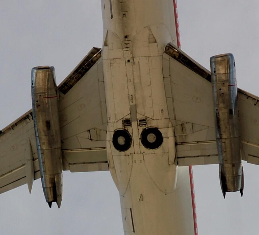
Nose wheel steering
Nose wheel steering works when the nose gear is down and compressed by the aeroplane's weight. Setting the gear lever down makes system A pressure available to the steering metering valve. The nose wheel steering wheel turns the nose wheels up to 78° either way and overrides the pedals; full rudder pedal travel gives up to 7° either way, and pedal steering is deactivated as the nose gear strut extends.
The guarded NOSE WHEEL STEERING switch selects the source: NORM uses system A, ALT uses system B. Alternate steering gives system B pressure to the nose wheels only with the switch at ALT, normal quantity in the system B reservoir and the aeroplane on the ground. If a leak downstream of the landing gear transfer valve drains system B fluid, a sensor closes the transfer valve and alternate steering is lost.
For pushback or towing, a nose gear steering lockout pin inserted in the towing lever depressurises the steering, so the aeroplane can be moved without depressurising the hydraulic systems. Without the pin, system A must not be pressurised, because unwanted tow bar movement can occur. During pushback the crew must not hold or turn the nose wheel steering wheel, nor use the brakes to stop the aeroplane.
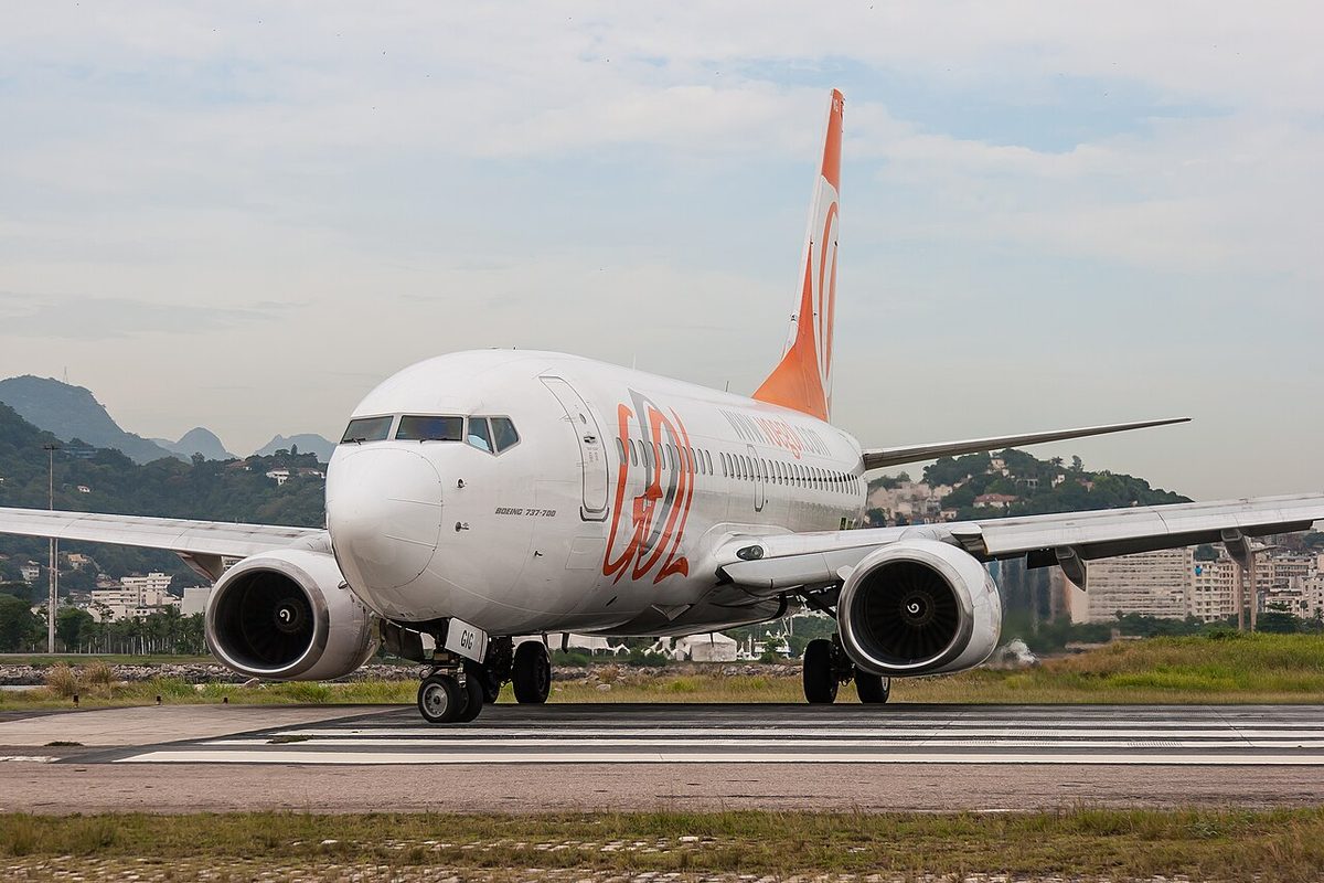
Normal and alternate brakes
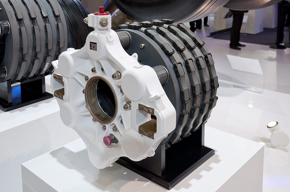
Each main wheel has a multi-disc hydraulic brake; the nose wheels have none. The brake pedals control the left and right brakes independently: pushing the top of the pedals brakes, full pedal travel steers.
- The normal brake system is powered by system B. It is the only one with autobrake.
- The alternate brake system is powered by system A. If system B is low or fails, system A automatically supplies the alternate brakes.
Both systems have antiskid. Brakes must not be applied before touchdown, which damages tyres and gear.
Brake accumulator and anti-skid
The brake accumulator is pressurised by system B. If both normal and alternate brake pressure are lost, the pressure trapped in it still gives several brake applications or a parking brake application. The HYD BRAKE PRESS indicator shows its pressure: normal 2,900 to 3,600 psi, maximum 3,600 to 4,000 psi, normal precharge 1,000 psi. Before start, brake pressure must be at least 2,800 psi.
The parking brake is set by fully depressing the brake pedals while pulling the PARKING BRAKE lever, which latches the pedals and closes the parking brake valve; it is released by depressing the pedals until the lever releases. It can be set with system A or B pressurised; otherwise the accumulator holds the pressure. A red light, powered from the battery, shows it is set. The crew must not assume the parking brake will prevent movement, because accumulator pressure can be insufficient. Advancing either forward thrust lever with it set brings the take-off configuration warning, and a parking brake fault can light ANTISKID INOP.
Antiskid gives skid, locked wheel, touchdown and hydroplane protection on both brake systems, and it remains available even with the loss of both hydraulic systems. The normal system protects each main wheel individually; the alternate system protects wheel pairs. The amber ANTISKID INOP light shows a fault detected by the antiskid monitoring.
Autobrake and RTO
The autobrake uses system B pressure to give maximum deceleration on a rejected take-off and preselected deceleration after touchdown. It works only when the normal brake system is functioning, with antiskid protection. The AUTO BRAKE select switch has OFF, RTO, 1, 2, 3 and MAX, the selector being pulled out to reach MAX.
The RTO autobrake mode arms with the aeroplane on the ground, antiskid and autobrake serviceable, the switch at RTO, wheel speed below 60 kt and the forward thrust levers at IDLE. It is selected on the preflight. If the thrust levers are retarded to idle at or above 90 kt, it applies maximum brake pressure. Below 90 kt no autobraking occurs and RTO stays armed. When both air/ground systems sense air mode, RTO disarms without lighting AUTO BRAKE DISARM, and the switch stays at RTO, so it is set to OFF after take-off. A landing made with RTO still selected gives no autobraking, and the light comes on two seconds after touchdown.
For landing, four levels of deceleration (1, 2, 3 and MAX) can be selected, though on a dry runway even MAX gives less deceleration than full manual braking. Braking starts when both forward thrust levers are at idle and the main wheels spin up. The system reduces brake pressure as the reversers and spoilers add their share, the level can be changed by turning the selector without disarming, and it brings the aeroplane to a stop unless the pilot ends it. A setting can still be selected after touchdown, before slowing through 30 kt.
The amber AUTO BRAKE DISARM light comes on when, during a rejected take-off or landing, the speed brake lever is moved to DOWN, manual braking is applied or a thrust lever is advanced (except in the first 3 seconds after touchdown); when a landing is made with RTO selected; for one to two seconds when RTO is selected on the ground; and when the autobrake has a fault. Turning the selector to OFF disarms it without the light. In a rejected take-off with RTO selected, the crew brake manually if the light comes on or deceleration is inadequate.
Exam tip: RTO arms below 60 kt and brakes from 90 kt; landing settings can be selected until 30 kt. Autobrake needs the normal brakes, so it is lost with system B.
Among the 737 MAX differences in the FSB report, three concern the gear: the lever has two positions, so there is no OFF to select after retraction; the nose gear is 8 in longer than the 737-800's, for the larger engines' ground clearance; and a MAINT light replaces the PSEU light.
Frequently asked questions
Which hydraulic systems power the Boeing 737 brakes?
The normal brakes are powered by system B and the alternate brakes by system A, which takes over automatically if system B is low or fails. Both have antiskid, but the autobrake works only with the normal brakes. If both systems are lost, pressure trapped in the brake accumulator, which system B charges, still gives several brake applications or a parking brake application.
How does the 737 RTO autobrake work?
RTO arms on the ground with antiskid and autobrake serviceable, the selector at RTO, wheel speed below 60 kt and the forward thrust levers at idle. If the thrust levers are retarded to idle at or above 90 kt, it applies maximum brake pressure. Below 90 kt there is no autobraking and RTO stays armed. It disarms when both air/ground systems sense air mode.
What does the AUTO BRAKE DISARM light mean on the 737?
The amber light shows the autobrake has disarmed because the speed brake lever was moved to DOWN, manual brakes were applied or a thrust lever was advanced during a rejected take-off or landing, or because a landing was made with RTO selected, or an autobrake fault exists. It also lights for one to two seconds when RTO is selected on the ground. Selecting OFF disarms the system without lighting it.
What is the landing gear lever lock on the 737?
On the ground a lever lock stops the landing gear lever being moved to UP. In flight the air/ground system energises a solenoid that releases the lock. An override trigger in the lever allows it to be raised anyway, bypassing the lock. The 737 NG lever has UP, OFF and DN positions; the 737 MAX lever has only two positions.
What does the 737 PSEU light mean?
The proximity switch electronic unit monitors the take-off and landing configuration warnings, the landing gear and air/ground sensing. Its amber light, on the aft overhead panel, shows on the ground a PSEU fault or an overwing exit flight lock that has not disengaged, with OVERHEAD and MASTER CAUTION. It is inhibited in flight, with thrust advanced for take-off and for 30 seconds after landing. On the MAX a MAINT light replaces it.
Test yourself on B737 Landing Gear and Brakes
The v1prep banks cover this topic in the B737 type-rating bank, with a worked explanation for every answer. EASA ATPL, PPL, IR and CPL, the FAA written tests and A320/B737 type ratings.
Start practising →Sources and further reading
- FAA Flight Standardization Board Report, Boeing 737, Revision 17
- EASA Type Certificate Data Sheet IM.A.120, Boeing 737
- EASA Easy Access Rules for Large Aeroplanes (CS-25), CS 25.729 and CS 25.735, retracting mechanism and brakes
- 14 CFR 25.729, Retracting mechanism
- 14 CFR 25.735, Brakes and braking systems
- FAA Aviation Maintenance Technician Handbook, Airframe (FAA-H-8083-31B), Aircraft Landing Gear Systems
Library articles are written for study and exam preparation. They do not replace your aircraft's approved documentation, your operator's procedures or the regulations themselves.