Fuel Quantity and Temperature Indication
Fuel quantity indication tells the crew how much fuel is in each tank: by a float that measures the level in light aircraft, or by capacitance probes that let a computer work out the fuel mass in transport aircraft. Fuel temperature indication shows whether the fuel is within its limits, especially after a long cold soak at altitude.
Fuel cannot be seen in flight, so the crew rely on instruments to tell them how much there is and where it is. Those instruments measure it indirectly: a float rides on the fuel surface, or probes sense how much of their length stands in fuel, and a gauge or computer converts the result into a quantity. Each method has its errors, and part of the pilot's skill lies in knowing them.
Temperature is watched for a different reason. Fuel that becomes too cold forms wax and ice that can block the engine's filters, and fuel that becomes too hot boils in the lines. Transport aircraft therefore display the fuel temperature and set limits on it, which matter most on long flights at high altitude. The quantity figures feed the fuel checks described in in-flight fuel management.
Float-type fuel gauges
Light aeroplanes measure the fuel volume with a float-type fuel gauge. A float on the fuel surface moves the wiper of a variable resistance, and an electrical indicator on the panel shows the level. The system is simple, but the float follows the fuel as it sloshes in manoeuvres and changes with attitude, and it cannot allow for changes in density.
Certification asked little of it. The former US rule on which most light aeroplanes in service were certified, 14 CFR 23.1337(b), required a means to indicate the usable fuel in each tank but fixed only one calibration point: the gauge must read zero in level flight when the fuel remaining equals the unusable fuel. Elsewhere on the scale the rule set no accuracy, and a float-type fuel quantity gauge may be well out. Since the 2017 rewrite of Part 23, 14 CFR 23.2430 requires a means for the crew to determine the total usable fuel available. An electrical failure also takes many light aircraft fuel gauges with it.
The most reliable way to know the fuel on board before flight is therefore to look into the tanks or use a calibrated dipstick, and then to track the fuel in flight by time and known consumption. A fuel totaliser, which subtracts the measured fuel used from a starting quantity entered by the pilot, is precise but blind to the tanks themselves, so gauges, totaliser and time are cross-checked (see sensors, transducers and system indicators).
Capacitance fuel quantity systems
Transport aircraft use a capacitance fuel quantity indication system, the fuel quantity indicating system (FQIS). Each tank contains several capacitance probes, each a pair of concentric aluminium alloy tubes held apart by insulators and supplied with alternating current. The fuel and the air between the tubes form the dielectric of a capacitor, and its capacitance depends on their relative permittivity:
| Substance | Relative permittivity (approx.) |
|---|---|
| Air | 1.0006 |
| Gasoline | 1.95 |
| Kerosene | 2.10 |
| Water | 81 |
As the fuel rises up a probe, more of the gap is filled with fuel and the capacitance increases. The probes in a tank are connected in parallel, which averages out the errors that attitude and sloshing would cause in a single sensor. A compensator, or reference unit, kept submerged in the unusable fuel, measures the permittivity of the fuel actually on board so that the probes' reading can be corrected. What the probes give is the fuel's height and so its volume; the computer multiplies the volume by the fuel's density to obtain the mass. Water is the weak point: with a permittivity nearly forty times that of kerosene, water around a probe makes the gauge over-read, sometimes beyond full scale. A capacitance system is also built to fail safe. If it fails, the pointer of an analogue indicator is driven slowly towards empty, because under-reading is safer than over-reading, and a test switch uses the same circuit to show the pointer falling and recovering.
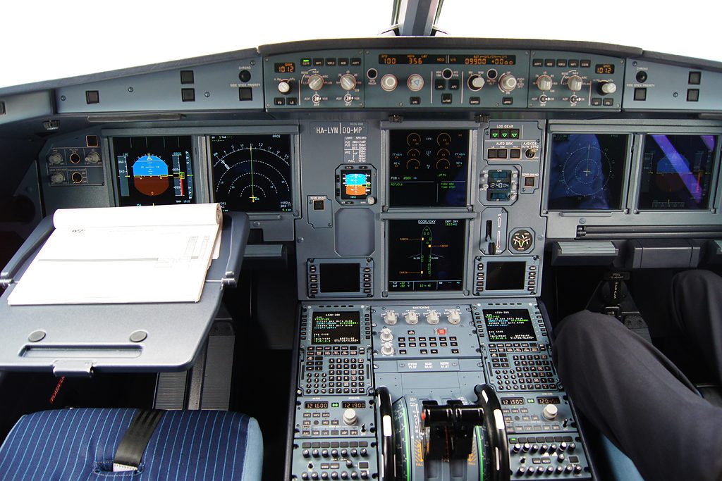
On the A320 the fuel quantity indicating computer has two channels, the second taking over automatically if the first fails. It sends the total fuel mass, the quantity in each tank and the fuel temperatures to the ECAM. If a tank's gauging degrades, dashes replace the last two digits of the fuel on board and published accuracy tolerances apply, from ±110 kg for one inner tank to +390 kg/−750 kg with all tanks affected. An amber half-box round the fuel on board warns that not all of it is usable, for example because a transfer valve has failed. The Boeing 737 displays the usable fuel in each tank and warns that each indication may be up to 2.0 % in error on the ground and 2.5 % in flight.
Mass, volume and specific gravity
Fuel specific gravity (SG) is the ratio of the mass of a volume of fuel to the mass of the same volume of water, numerically the density in kg/l: about 0.72 for avgas and 0.79 to 0.82 for kerosene. It falls as the fuel warms, so a tank of warm fuel holds less mass than the same tank of cold fuel. Because an engine's energy comes from the mass of fuel it burns, mass is what the fuel plan and performance data need.
A float gauge reads volume and makes no allowance for this. A capacitance system can, and the A320 measures the density directly with a densitometer, the cadensicon, in each inner tank; if it fails, a capacitance index compensator supplies the fuel's permittivity, from which the density is estimated. Tank capacities in the manuals are quoted at a stated reference density: 0.785 kg/l for the A320 and 0.8029 kg/l for the Boeing 737 NG. The conversions themselves, and the classic errors in them, are covered in fuel mass and fuel loading.
Dripsticks and magnetic level indicators
When the gauging system fails, or its reading needs checking before dispatch, the fuel is measured mechanically. Three devices have been used:
- The dipstick, a calibrated stick put into the tank from the top, the method of light aircraft; on a large wing it means working at height on a slippery surface.
- The dripstick, a calibrated hollow tube withdrawn downwards through a fuel-tight fitting in the lower skin. When its open top falls below the fuel surface, fuel drips from it, and the length withdrawn gives the level.
- The magnetic level indicator (MLI), or dropstick, now preferred. A calibrated rod with a magnet at its tip slides in a fuel-tight tube, and a float carrying another magnet rides on the fuel surface outside it. The rod is lowered until the two magnets engage, and the length protruding below the wing gives the fuel level.
The readings are turned into volume with the manufacturer's tables and into mass with the fuel density. The Boeing 737 has six such fuel measuring sticks in each main tank and four in the centre tank: each is withdrawn until it latches magnetically to its internal float, and the depth is read where it passes through the wing skin. The Embraer E190 E1 has wing magnetic level indicators; the E2 does not.
Low-level warnings
Airliners do not rely on the quantity indication alone to warn of a low tank. A separate low-level sensor, in its simplest form a low level float switch that closes a circuit when the fuel falls below it, gives a warning that is independent of the gauging. On the A320 the FUEL WING TK LO LVL warning comes on when a wing tank holds less than 750 kg, triggered by a level sensor that is totally independent of the displayed quantity. The Boeing 737's amber LOW alert appears below 907 kg in a main tank and stays until the tank holds 1,134 kg again. On the E190-E2 a master warning, FUEL LO LEVEL, appears below 400 kg in a wing tank.
Some limitations build on the same warnings. The A320 may not take off with less than 1,500 kg of fuel, or with a wing tank low-level alert displayed. For the A320neo, EASA's certification basis goes further, requiring a low fuel level warning for every tank or collector cell that should not be emptied in normal operation, provided in time for a safe landing and unaffected by any single failure that could corrupt the normal gauging. It also calls for alerts on abnormal fuel management and possible leaks; means EASA has accepted include a fuel used/fuel on board disagreement alert, a lateral imbalance alert and a comparison of the two engines' fuel flows.
Fuel temperature indication and limits
Fuel temperature indication comes from sensors in the tanks. The Boeing 737 has one in main tank 1, shown on the FUEL TEMP indicator of the fuel panel. The A320 shows fuel temperatures on the ECAM FUEL page, each one whenever its sensor is wet, and the E190-E2 monitors the left tank. Fuel temperature limits depend on the aircraft and the grade:
| Aircraft and fuel | Maximum | Minimum |
|---|---|---|
| Boeing 737 NG | 49 °C | −43 °C, or 3 °C above the freezing point of the fuel in use, whichever is higher |
| A320, Jet A-1, JP-8, No. 3 Jet | 54 °C | −43 °C |
| A320, Jet A | 54 °C | −36 °C; monitor fuel temperature once TAT reaches −34 °C |
| A320ceo, Jet B, JP-4 | 49 °C | −54 °C for JP-4 |
The A320 also gives advance notice: in flight phases 2 and 6 of its warning system (on the ground before take-off power, and in flight between the take-off and landing phases), an advisory appears on the FUEL page when the fuel is warmer than 45 °C in an inner cell or 55 °C in an outer cell, or colder than −40 °C, and beyond the limits the indication turns amber with a caution. On the E190-E2 a FUEL TANK LO TEMP caution appears at −37 °C. Hot fuel risks boiling and pump cavitation at low pressure, and the volatile wide-cut fuels have the lowest maximum; cold fuel risks wax and ice (see aviation fuel grades and properties). When grades are mixed, the published minimums for the individual grades no longer apply, so the freezing point of the fuel actually loaded matters. A fuel system icing inhibitor acts on water, not wax, and the 737's limitations state that it does not change the minimum.
Cold-soaked fuel
On a long flight at high altitude the fuel in the wing tanks undergoes a cold soak: it cools steadily, and can fall to between about −20 °C and −40 °C. It cools towards the temperature of the boundary layer over the wing skin, which is close to, and slightly below, the total air temperature (TAT). TAT is higher than the outside air temperature by the ram rise, which increases with Mach number (see air data computer and air temperature). This is why the A320's Jet A limitation is tied to TAT, and why the remedies for fuel approaching its limit are to descend to warmer air or to increase the Mach number. Long polar and ultra long range flights watch fuel temperature closely, and engines warm the fuel ahead of their filters, usually in a fuel-cooled oil cooler (see gas turbine engine fuel system).
Cold fuel also hides water. On 17 January 2008 British Airways Flight 38, a Boeing 777 arriving from Beijing, landed short of the runway at London Heathrow after an uncommanded reduction in thrust on both engines during the final approach. The AAIB found that, over a long period of low fuel temperatures, ice had accumulated in the fuel system and was then released, restricting the fuel flow to both engines, although the fuel met every standard, including that for water content (see thrust levers, idle modes and engine handling). EASA's special condition for the A320neo now requires either that water and ice stay evenly dispersed in the fuel, or that the whole fuel system, engine included, tolerates such a sudden release.
The cold stays with the aircraft after landing. Fuel that is still cold-soaked keeps the wing skin above it cold, and in humid air frost forms there even when the air temperature is above freezing: cold-soaked fuel frost, which must be removed before take-off unless the manufacturer's procedures allow a limited amount (see aircraft ground de-icing and anti-icing).
Exam tip: float gauges measure volume and suffer manoeuvre errors; capacitance systems indicate mass (probe volume times density), average attitude errors with probes in parallel, fail towards empty and over-read with water. Low-level warnings are independent of the gauging. The minimum fuel temperature keeps a margin above the freezing point, and too-cold fuel is warmed by descending or increasing Mach.
Frequently asked questions
How does a capacitance fuel quantity system work?
Probes made of concentric tubes stand in each tank and act as capacitors, with fuel and air as the dielectric between the tubes. Kerosene has a relative permittivity of about 2.1 against about 1 for air, so the capacitance rises as the fuel level rises. Many probes in parallel average out attitude errors and a compensator corrects for the fuel's own permittivity. The probes give the fuel volume, and the computer multiplies it by the fuel density to give the mass.
Why do light aircraft fuel gauges read inaccurately?
Most measure the level with a float that moves a variable resistance. The float moves as fuel sloshes in manoeuvres and with attitude, and it measures volume without allowing for density. The former US certification rule, 14 CFR 23.1337(b), still the basis of most light aircraft, fixed only one calibration point: zero in level flight when the usable fuel is gone. Pilots therefore check the tanks visually or with a dipstick.
What is a dripstick or magnetic level indicator?
Both are mechanical ways of measuring the fuel level from under the wing when the gauging system is unavailable or needs checking. A dripstick is a calibrated hollow tube withdrawn until fuel drips from it. A magnetic level indicator, or dropstick, is a calibrated rod that is lowered until a magnet in its tip meets a magnet on a float; the length exposed gives the level, converted to mass with tables and the fuel density.
What is the minimum fuel temperature for Jet A-1?
The specification freezing point of Jet A-1 is −47 °C, and aircraft limits keep a margin above it. The Boeing 737 allows −43 °C or 3 °C above the freezing point of the fuel in use, whichever is higher, and the A320 −43 °C. With Jet A, whose freezing point is −40 °C, the A320's limit is −36 °C. A fuel system icing inhibitor does not change these limits.
What do pilots do if the fuel gets too cold in flight?
Fuel in the wing cools on long flights at high altitude, towards the temperature of the boundary layer over the wing skin, which is close to, and slightly below, the total air temperature. If the fuel temperature approaches the limit, the crew raise the total air temperature by descending to warmer air or by increasing the Mach number, which increases the ram temperature rise. Long polar and ultra long range flights watch fuel temperature closely for this reason.
Test yourself on Fuel Quantity and Temperature Indication
The v1prep banks cover this topic in Aircraft General Knowledge (021), with a worked explanation for every answer. EASA ATPL, PPL, IR and CPL, the FAA written tests and A320/B737 type ratings.
Start practising →Sources and further reading
- FAA Aviation Maintenance Technician Handbook, Airframe (FAA-H-8083-31B), Chapter 14, Aircraft Fuel System (fuel system indicators)
- FAA Pilot's Handbook of Aeronautical Knowledge (FAA-H-8083-25), Chapter 7, Aircraft Systems
- 14 CFR 23.2430, Fuel systems
- EASA Easy Access Rules for Large Aeroplanes (CS-25), CS 25.1305 Powerplant instruments and CS 25.1337
- EASA TCDS EASA.A.064 (Airbus A318/A319/A320/A321), Explanatory Note, Annex I, Special Conditions E-37 Water/Ice in Fuel System and F-13 Fuel System Low Level Indication
- AAIB Aircraft Accident Report 1/2010, Boeing 777-236ER G-YMMM, London Heathrow, 17 January 2008
Library articles are written for study and exam preparation. They do not replace your aircraft's approved documentation, your operator's procedures or the regulations themselves.