Sensors, Transducers and System Indicators
A transducer converts a physical quantity, such as pressure, position, rotational speed or fuel level, into another form, usually an electrical signal, so that it can be transmitted to a remote indicator or a computer. System indicators display the result to the flight crew.
Every number on a flight deck starts as a physical quantity somewhere else in the aircraft: an oil pressure in the engine, a flap position in the wing, a shaft speed in the core, a fuel level in the tank. A transducer converts that quantity into a signal that can be carried to the flight deck, and an indicator or a computer display turns the signal back into something the crew can read. Understanding the chain explains both the readings and their failures.
The subject is examined under instrumentation and aircraft systems in the EASA ATPL and CPL syllabus, and at a simpler level in the PPL, where the ammeter, the fuel gauges and the tachometer are the pilot's main view of the aircraft's health. Engine and fuel indications are treated in more detail in engine indications and condition monitoring and fuel quantity and temperature indication.
Transducer principles
A measuring chain has three parts: a sensing element that responds to the quantity, a transmitter that turns the response into a signal, and an indicator or computer input. Remote transmission keeps oil, fuel and hydraulic lines out of the flight deck and lets one sensor feed several displays, computers and the flight recorders.
Many transducers work by electromagnetic induction. Faraday's law states that the electromotive force induced in a coil is proportional to the number of turns and to the rate of change of the magnetic flux linking it; a steady flux induces nothing. That single principle drives the LVDT, the synchro, the tachometer generator and the phonic wheel described below, and the flux valve of the remote compass (see electromagnetism and induction). AC transducers such as synchros are commonly fed from a 26 V AC instrument supply.
Temperature follows the same pattern. Gas turbine exhaust temperature is measured by thermocouples of chromel and alumel, which generate their own small voltage; several probes around the jet pipe are connected in parallel, so the reading is their average and one failed probe changes it only slightly. The direct-reading air thermometer of a light aeroplane is a bimetallic strip of invar and brass wound into a helix.
Pressure sensing elements
| Element | Construction | Range | Typical use |
|---|---|---|---|
| Diaphragm | A corrugated metal disc held at its edge, deflecting under pressure | Low | Small pressure differences |
| Capsule | Two diaphragms joined at their edges; sealed (aneroid) or open to a pressure | Low, very sensitive | Altimeter, airspeed indicator, VSI |
| Pressure bellows | A stack of joined diaphragms that extends and contracts | Low, high or differential | Pressure transmitters, such as fuel booster pump output |
| Bourdon tube | A curved tube of oval cross-section, sealed at one end | High | Engine oil pressure |
A Bourdon tube is the oldest pressure element. Pressure admitted to the open end tries to straighten the curve, and a linkage magnifies the movement of the sealed end to turn a pointer. Capsules are the heart of the pitot-static instruments: the airspeed indicator's capsule receives pitot pressure inside and static pressure outside, so it expands with dynamic pressure (see pitot-static system). Some vertical speed indicators have diaphragm overload stops, mechanical limits that stop the capsule being damaged by a climb or descent rate beyond its calibrated range.
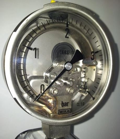
In a remote-reading gauge the element does not drive the pointer directly. It moves the core of a transformer, the rotor of a synchro or the wiper of a potentiometer at the engine, and only the electrical signal travels to the flight deck.
LVDT and RVDT position sensors
A linear variable differential transformer (LVDT) measures straight-line position without any sliding contact. A primary coil fed with AC sits between two secondary coils wound in opposition, and a soft iron core, attached to the moving part, slides inside them. With the core central, the voltages induced in the two secondaries are equal and opposite and the output is zero. When the core moves, one secondary couples more strongly than the other: the amplitude of the output grows in proportion to the displacement, and its phase relative to the excitation shows the direction.
With no sliding contact to wear, LVDTs suit feedback from actuators. In a yaw damper, for example, an LVDT on the rudder actuator reports the rudder position back to the computer, so the loop can stop the rudder at the commanded deflection and return it to neutral. The rotary variable differential transformer (RVDT) applies the same principle to angles, such as the position of a lever, a control column or a control surface.
Synchro remote transmission
A synchro, also called a Selsyn, transmits an angle electrically. In the transmitter a rotor on the measured shaft is excited with constant AC. Its field induces voltages in three stator coils, 120° apart, whose ratio depends on the rotor angle. Three wires carry these voltages to the stator of a receiver, which reproduces the same field direction.
- In a torque synchro the receiver rotor, excited from the same supply, simply turns into line with the field and drives a pointer.
- In a control synchro the receiver's rotor produces an error voltage whenever it is not at right angles to the field. At the null, with the rotor perpendicular to the field, no voltage is induced and the system is synchronised; otherwise the error is amplified to drive a servo motor until the null returns.
Synchros carried heading from the gyromagnetic compass to the RMI, the autopilot and the flight management system, and they still transmit angles such as the vane position of an angle of attack sensor.
Tachometers and phonic wheels
Engine speed is measured in three ways:
- Mechanical (magnetic drag cup). A flexible drive turns a magnet inside a metal cup; eddy currents drag the cup round against a hairspring, moving the pointer. It survives only on older piston aircraft.
- Tachometer generator. A small three-phase AC generator driven by the engine produces a frequency proportional to shaft speed. In the indicator a motor driven by that supply turns a magnet inside a drag cup to move the pointer, so the reading depends on the frequency rather than the voltage.
- Inductive speed probe and phonic wheel. A probe containing a coil and magnet faces a toothed phonic wheel on the shaft, or the fan blades themselves. Each tooth passing changes the magnetic flux and, by Faraday's law, induces a pulse; the pulse frequency is proportional to the shaft speed.
Gas turbine speeds, N1 and N2, are displayed as a percentage of a reference speed. The same inductive principle serves elsewhere: a wheel speed transducer in each main wheel axle feeds the anti-skid system, an electronic torquemeter compares the phase of pulses from toothed wheels on a torque shaft and a reference shaft, and a fuel flowmeter's magnetised impeller induces a signal whose frequency is proportional to the flow.
Fuel quantity and totaliser
Light aeroplanes measure fuel volume with a float that moves the wiper of a variable resistance. The system is simple, but it suffers from manoeuvring and attitude errors and cannot allow for changes in fuel density.
Transport aircraft measure fuel mass with capacitance probes, each a pair of concentric aluminium alloy tubes held apart by insulators. Between the tubes, fuel and air together form the dielectric. The dielectric constant, or relative permittivity, of a material is the factor by which it raises a capacitor's capacitance compared with a vacuum:
| Material | Relative permittivity (approximate) |
|---|---|
| Air | 1.0006 |
| Aviation gasoline | 1.95 |
| Kerosene | 2.10 |
| Water | 81 |
As the fuel level rises, more of the gap is filled with fuel and the capacitance rises. Many probes in each tank are connected in parallel, which averages out attitude errors. A compensator (reference unit), kept submerged in unusable fuel, measures the fuel's own permittivity so the system can correct for variations, and with the density the computer converts volume to mass. The A320 measures the density with a densitometer called a cadensicon in each inner wing tank, backed up by a capacitance index compensator. Water in a tank, with its far higher permittivity, makes a capacitance gauge over-read, sometimes beyond full scale.
A fuel totaliser works differently. It subtracts the fuel used, integrated from the fuel flow transmitters, from a starting quantity entered by the pilot. It is precise but blind to what is really in the tanks: a wrong entry, or a leak upstream of the flowmeters, goes unseen. Airline displays show both the gauged fuel on board and the fuel used per engine, and pilots of every category cross-check the two.
Ammeters and loadmeters
An ammeter is connected in series, so the whole current passes through it; a voltmeter is connected in parallel. Light aircraft use one of two arrangements:
- A centre-zero ammeter in the battery circuit shows current into the battery (charge, to the right of zero) or out of it (discharge, to the left). After an engine start it shows a high charge that tapers off as the battery recovers, then settles near zero.
- A loadmeter in the alternator or generator output reads only positive values and shows the total load that source carries.
An alternator failure shows as a steady discharge on the ammeter, or a loadmeter at zero, usually with a low-voltage light: the battery is now carrying the load. In a light twin, a failed alternator shows as a zero reading on its own meter while the other alternator's rises. On the Boeing 737 the DC voltmeter and ammeter can read the battery and each of the three transformer-rectifier units.
Position and status indicators
Landing gear position is sensed by microswitches or, on modern aircraft, by contactless inductive or capacitive proximity sensors, on the uplocks and downlocks. The standard display is a green light for each gear down and locked, red for gear in transit, and no lights for gear up and locked. Bulbs are duplicated so that one blown bulb cannot give a false picture. Similar proximity sensors on the landing gear shock struts provide the air/ground logic that many systems use.
Control position indicators show surface and trim positions. The Boeing 737's flap position indicator shows the left and right trailing edge flaps and so reveals an asymmetry, and its flight control surface position indicator shows, among other surfaces, the elevators, the rudder and two of the flight spoilers. Other glass cockpits show surface positions on an ECAM system page or the EICAS status page.
The doll's eye indicators of older flight engineer panels, small indicators that showed states such as a valve's position, have largely been replaced by ECAM and EICAS mimic diagrams. On the A320's ECAM pages, for example, a valve drawn in line with the flow is open and one drawn across it is closed.
Exam tip: Bourdon tube for high pressure, capsule for low pressure, bellows for low, high or differential pressure. Capacitance gauges read mass and over-read with water; float gauges read volume.
Frequently asked questions
What is a Bourdon tube?
A Bourdon tube is a pressure-sensing element made from a curved metal tube with an oval or elliptical cross-section, closed at one end. Pressure admitted to the open end tries to straighten the curve, and the movement of the closed end is magnified by a linkage to drive a pointer. It is the oldest type of pressure element and is used for high pressures, such as engine oil pressure.
How does a capacitance fuel gauge work?
Each tank contains probes made of concentric tubes that act as capacitors. Fuel and air fill the gap between the tubes as the dielectric. Fuel has a dielectric constant of about 2.1 against about 1 for air, so the capacitance rises as the fuel level rises. A compensator immersed in fuel corrects for changes in the fuel's permittivity, and with the fuel density the system indicates the mass of fuel, which is what performance calculations need.
What is the difference between an ammeter and a loadmeter?
A centre-zero ammeter is connected to the battery and shows the direction and size of the current flowing into or out of it: to the right of zero while the battery is charging, to the left when it is discharging. A loadmeter is connected in the alternator or generator output, reads only positive values and shows the total load that source is carrying. After an alternator failure the ammeter shows a discharge and the loadmeter drops to zero.
What is an LVDT?
A linear variable differential transformer measures straight-line position without contact. An AC-excited primary coil and two secondary coils, wound in opposition, surround a movable iron core attached to the part being measured. With the core central the secondary voltages cancel; as it moves, the output grows in proportion to the displacement and its phase shows the direction. The rotary version, the RVDT, measures angles.
What is a fuel totaliser?
A fuel totaliser computes the fuel remaining by subtracting the fuel used, measured by the fuel flow transmitters, from a starting quantity entered by the pilot. It is precise but cannot see what is actually in the tanks, so a wrong entry or a leak upstream of the flowmeter goes unnoticed. Pilots therefore cross-check the totalizer against the tank gauges and a physical check of the fuel before flight.
Test yourself on Sensors, Transducers and System Indicators
The v1prep banks cover this topic in Instrumentation (022), with a worked explanation for every answer. EASA ATPL, PPL, IR and CPL, the FAA written tests and A320/B737 type ratings.
Start practising →Sources and further reading
- EASA, Explanatory Note to ED Decision 2018/001/R, Part-FCL theoretical knowledge learning objectives (021 Airframe and Systems, 022 Instrumentation)
- FAA Pilot's Handbook of Aeronautical Knowledge (FAA-H-8083-25), Chapter 7, Aircraft Systems, and Chapter 8, Flight Instruments
- FAA Aviation Maintenance Technician Handbook, Airframe (FAA-H-8083-31), Aircraft Instrument Systems
- FAA Instrument Flying Handbook (FAA-H-8083-15B), Chapter 5, Flight Instruments
Library articles are written for study and exam preparation. They do not replace your aircraft's approved documentation, your operator's procedures or the regulations themselves.