Gas Turbine Engine Fuel System
The engine fuel system takes fuel from the aircraft's tank feed and delivers it clean, free of ice and at high pressure to the fuel control and the spray nozzles. It comprises the engine-driven LP and HP pumps, heat exchangers, filters, the LP and HP shut-off valves and the fuel manifold.
The engine fuel system of a gas turbine takes over the fuel where the aircraft's tank system hands it on and carries it to the combustion chamber. On the way it raises the pressure far above what the tank boost pumps provide, warms the fuel so that ice cannot block the filters, filters it, and passes it to the fuel control, which meters exactly the flow the engine needs. Two shut-off valves, one at the wing and one at the engine, allow the flow to be stopped.
Fuel is more than the engine's energy. It lubricates the pumps and the fuel control, it drives their servo valves, and it is the heat sink into which the engine oil and, on the A320 and the 737, the generator drive oil get rid of their heat. The metering logic belongs to the engine control (see FADEC and engine fuel control), the nozzles to the combustion chamber, and the tanks, boost pumps and crossfeed to the aircraft (see fuel feed, boost pumps and crossfeed). This article follows the fuel between them.
Engine fuel system layout
The components differ from engine to engine, but their functions follow a fairly standard order:
- Tank boost pumps, part of the aircraft system, push fuel to the engine feed line.
- The LP fuel shut-off valve, or spar valve, where the feed line leaves the wing.
- The engine's LP fuel pump, which raises the pressure enough to feed the rest of the system.
- Heat exchangers in which hot oil warms the fuel, and in some designs a separate fuel heater.
- The LP fuel filter, with its bypass valve.
- The HP fuel pump, which provides the pressure the fuel control and the spray nozzles need.
- The fuel control unit (FCU), on FADEC engines the hydromechanical unit (HMU), which meters the flow.
- The HP fuel shut-off valve, the fuel flowmeter and the fuel manifold, which feeds the spray nozzles.
The Boeing 737 NG shows a real installation. Fuel passes the spar valve and the first stage of the engine fuel pump, which raises its pressure, then two fuel/oil heat exchangers in which the IDG oil and the engine oil heat it, then a fuel filter. The EEC meters the fuel through the HMU, and the fuel flow is measured after it has passed the engine fuel shut-off valve.
Not all the fuel goes to the burners. On the A320, some high-pressure fuel flows through the IDG heat exchanger, where it cools the generator drive oil, and returns through a FADEC-controlled fuel return valve to the outer wing tank (see AC generators, CSD and IDG).
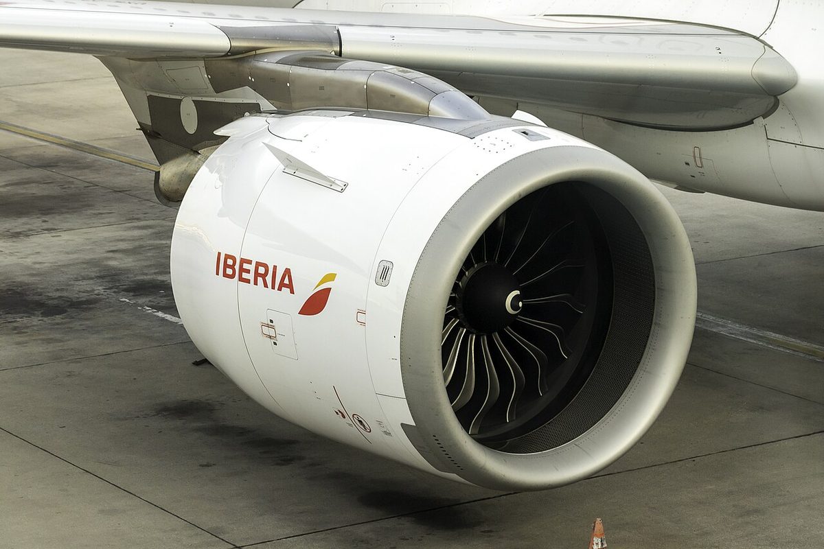
LP and HP fuel pumps
Upstream of the engine, the tank boost pumps deliver fuel under positive pressure. At altitude fuel boils at a lower temperature, and an engine pump that had to suck fuel from the tank would lower the pressure further and invite vapour locks. If the boost pumps fail, the engine can usually still draw fuel: the Boeing 737 has a suction feed line that bypasses the pumps, and the A320's inner tanks gravity-feed their engines through suction valves. In the climb, however, air coming out of solution can collect in the suction line, and the 737 manual warns of thrust deterioration or flameout at high altitude.
The engine's LP fuel pump raises the pressure of the incoming fuel; on the Boeing 737 NG it is the first stage of the engine fuel pump. It keeps the heat exchangers, the filter and the HP pump inlet supplied with fuel under pressure, because an engine pump that has to suck its fuel at low pressure risks cavitation.
The HP fuel pump is an engine-driven pump, turned by the high-pressure spool through the accessory gearbox. On engines with two external gearboxes, the fuel and oil pumps are grouped on the high-speed one driven by the HP shaft, because the starter turns the HP spool first and these pumps must be running before the engine lights up. Because it is driven mechanically, the pump needs no electrical power. Its weakness is the start: turning slowly, it cannot produce the 1,500 to 2,000 psi that a plain fixed-orifice spray nozzle needs to atomise, which is why engines use nozzles that atomise well at small flows.
The HP pump of the CFM56-5B is a gear pump, a positive-displacement type driven by the HP shaft through the gearbox. A bypass valve round the fuel metering valve holds a constant pressure drop across it, so that the metered flow depends only on the valve's position. Metering, and the governors of older hydromechanical systems, are covered in FADEC and engine fuel control.
Fuel also lubricates the rubbing surfaces of the pumps and the fuel control. Kerosene is a poor lubricant on its own, so a lubricity additive can be used to reduce wear (see aviation fuel grades and properties).
Exam tip: The HP fuel pump is driven by the HP (N2) spool through the external gearbox. Adding an accessory load to that gearbox, such as a further hydraulic pump, takes power from the engine and so increases its specific fuel consumption.
LP and HP shut-off valves
Two valves in series can stop the fuel, and they do different jobs.
The LP fuel shut-off valve, also called the LP valve, LP cock or spar valve, sits where the fuel leaves the tank system, at the wing spar near the engine. It isolates the engine, and the fuel lines running through its fire zone, from the tanks. On the Boeing 737 the spar fuel shut-off valve is in the wing leading edge outboard of the pylon, driven by a DC motor powered from the hot battery bus. On the A320 the LP valve is closed by the ENG MASTER switch or by the ENG FIRE pushbutton; the ECAM FUEL page shows it in line in green when open and across the line in amber when closed.
The HP fuel shut-off valve, also called the HP valve, HP fuel cock or engine fuel shut-off valve, sits at the engine, downstream of the fuel control. It is the valve that normally starts and stops the engine. On the A320 it is in the HMU: setting the ENG MASTER switch to ON opens the LP and HP valves, and setting it to OFF sends close signals directly to both, bypassing the FADEC, so the engine can be shut down even with a FADEC failure. The amber FAULT light on the ENG MASTER panel comes on if the HP valve disagrees with its commanded position. On the 737 the engine fuel shut-off valve is fuel-actuated and solenoid-controlled, powered from the battery bus. Moving the start lever to IDLE opens both the spar valve and the engine valve, and moving it to CUTOFF, or pulling the engine fire switch, closes both. The blue ENG VALVE CLOSED and SPAR VALVE CLOSED lights show dim when the valve is closed and bright while it is moving or disagrees with the lever or fire switch.
The two valves are not interchangeable. The HP valve stops combustion at once, because it is close to the nozzles. The LP valve isolates the fuel system upstream, but leaves fuel between itself and the nozzles: on the A320, the ENG FIRE pushbutton closes only the LP valve, and an engine at ground idle then runs for about 60 seconds on the fuel trapped downstream. That is why the A320 fire drill sets the ENG MASTER switch OFF before the fire pushbutton is pushed (see engine failure and engine fire).
Fuel heating
Jet fuel always carries some dissolved and suspended water. As the fuel cools in the cruise, water comes out of solution and can freeze into ice crystals that block the filters. At still lower temperatures heavy hydrocarbons come out as wax crystals, which can clog the filter and upset the fuel control; the specification freezing points are −47 °C for Jet A-1 and −40 °C for Jet A. The 737's limit for tank fuel temperature, before take-off and in flight, is −43 °C or 3 °C above the freezing point of the fuel in use, whichever is higher, and a fuel system icing inhibitor does not change that limit (see fuel additives and contamination).
Engines therefore warm the fuel before it reaches the filter. The usual heat source is the engine oil, in a fuel-cooled oil cooler (FCOC), also called a fuel/oil heat exchanger: oil and fuel pass through a matrix, the oil gives up heat and the fuel takes it. The same device cools the oil and heats the fuel, continuously, whenever the engine runs; the A320 has no crew fuel heat selector. Some designs described in the ATPL texts add a fuel heater after the FCOC that uses hot compressor delivery air to melt any remaining ice crystals, brought in automatically when the filter approaches blocking, or on a fixed schedule.
On the CFM56-5B, the fuel leaving the HP pump divides into two streams. Unfiltered fuel goes straight to the fuel metering valve, while a filtered stream supplies the servo fuel heater and the servo valves of the HMU.
Certification rules test for water deliberately. CS 25.951(c) requires the fuel system to work with fuel saturated with water at 26.7 °C (80 °F), plus 0.20 cm³ of free water per litre (0.75 cm³ per US gallon), cooled to the most critical icing condition. Compliance used to assume that the water stayed evenly dispersed. The 2008 accident to a Boeing 777 at London Heathrow showed that, after a long period of low fuel temperatures, ice can build up in the tanks or engine feed system and then be released, restricting the fuel flow to both engines. EASA's special condition for the A320neo therefore requires Airbus either to show that the water or ice stays evenly dispersed, or to show that the whole fuel system, engine included, tolerates such a sudden release of ice.
Fuel filters and bypass
Coarse strainers at the boost pump inlets keep tank debris out of the pumps; fine filtering is done at the engine. CS 25.997 requires a strainer or filter between the tank outlet and either the fuel metering device or an engine-driven positive-displacement pump, whichever comes first. In the classic layout of the ATPL texts, the LP fuel filter sits downstream of the fuel heating and upstream of the HP pump. The LEAP-1A of the A320neo is an exception: a strainer protects the HP pump inlet and the main filter sits downstream of the HP pump, both bypassed and monitored, an arrangement EASA accepted as providing an equivalent level of safety.
A filter can block with ice, dirt or the microbial growth that forms at the fuel-water interface. As it clogs, the pressure difference across it rises. At a preset value a fuel filter bypass valve opens and lets fuel flow round the filter: unfiltered fuel is a risk to the pumps and the fuel control, but fuel starvation would stop the engine. Crews are warned before the bypass opens. The 737's amber FILTER BYPASS light shows an impending bypass caused by a contaminated filter; on the E190-E2 the equivalent is the ENG 1(2) FUEL IMP BYPASS caution, while an impending oil filter bypass gives only an advisory. After a bypass, the filter must be cleaned or replaced before the next flight.
Note: Do not confuse the fuel filter bypass with the fuel-cooled oil cooler's oil bypass valve. The latter protects the oil side of the cooler when the matrix is blocked or the oil is very viscous (see engine lubrication systems).
Fuel manifold
After metering, the fuel passes the HP shut-off valve and the fuel flowmeter, which feeds the fuel flow and fuel used indications (see engine indications and condition monitoring). It then enters the fuel manifold, which distributes it to the individual spray nozzles. The CFM56-5B has 20 nozzles; a burner staging valve supplies 10 of them permanently and the other 10 only when a high fuel-air ratio is needed, and if the fuel control fails a safety function supplies all 20 (see combustion chambers and turbines).
Small quantities of fuel, oil and hydraulic fluid from seals and drains in the nacelle are carried overboard through the drain mast under the nacelle. A trace of staining is normal; a steady stream or drip indicates an internal leak. A fuel leak reported from the drain mast during start has its own procedure (see ground handling, pushback and engine start).
A leak between the tanks and the flowmeter is not counted in the fuel used indication, so in flight it shows up as fuel used plus fuel remaining falling short of the fuel on board at departure. That is why crews compare the figures regularly (see in-flight fuel management).
Frequently asked questions
What is the difference between the LP and HP fuel shut-off valves?
The LP valve, or spar valve, sits where the fuel leaves the wing tanks and isolates the engine and its fuel lines from them, which is why the fire handle closes it. The HP valve, or HP fuel cock, sits at the engine downstream of the fuel control and normally starts and stops the engine. On the Boeing 737 the start lever and the fire switch each close both valves; on the A320 the engine master switch closes both, the fire pushbutton only the LP valve.
How is the HP fuel pump of a jet engine driven?
Mechanically, by the high-pressure spool through the accessory gearbox. Because the starter turns the HP spool first, the pump is already turning when fuel is introduced, and it needs no electrical power. At start the gearbox turns slowly, so the pump cannot produce the 1,500 to 2,000 psi a plain fixed-orifice nozzle needs; engines therefore use nozzles that atomise well at low flows. On the CFM56-5B of the A320 the HP pump is a gear pump.
Why is fuel heated before it reaches the engine filter?
Jet fuel always contains some water. As the fuel cools at altitude, the water comes out of solution and can freeze into ice crystals that block the filter, and at still lower temperatures wax crystals appear. Engines therefore warm the fuel ahead of the filter, usually in a fuel-cooled oil cooler, where hot engine oil gives up its heat to the fuel. Some designs described in the ATPL texts add a fuel heater that uses hot compressor delivery air.
What happens when an engine fuel filter becomes blocked?
As ice, contamination or microbial growth clogs the filter, the pressure difference across it rises. Before the bypass opens the crew are warned, for example the FILTER BYPASS light of the Boeing 737 or the ENG FUEL IMP BYPASS caution of the E190-E2. If the blockage continues, a bypass valve opens and unfiltered fuel flows round the filter, because contaminated fuel is less dangerous than no fuel at all.
Can a jet engine keep running if the tank boost pumps fail?
Usually, yes. The engine-driven pump can draw fuel from the tank by suction, and many types add a suction feed line that bypasses the failed pumps, or gravity feed through suction valves as on the A320's inner tanks. The weakness is altitude: in the climb, air comes out of solution in the fuel and can collect in the suction line, and the 737 manual warns of thrust deterioration or flameout at high altitude.
Test yourself on Gas Turbine Engine Fuel System
The v1prep banks cover this topic in Aircraft General Knowledge (021), with a worked explanation for every answer. EASA ATPL, PPL, IR and CPL, the FAA written tests and A320/B737 type ratings.
Start practising →Sources and further reading
- FAA Aviation Maintenance Technician Handbook, Powerplant (FAA-H-8083-32B)
- EASA, Explanatory Note to ED Decision 2018/001/R, Part-FCL theoretical knowledge learning objectives (021 Powerplant)
- EASA Easy Access Rules for Large Aeroplanes (CS-25), CS 25.951 to CS 25.1001, fuel system
- EASA TCDS EASA.A.064, Annex I, Special Conditions and Equivalent Safety Findings (E-37 Water/Ice in Fuel System, E-49 LEAP-1A Fuel Filter Location)
- EASA Easy Access Rules for Engines (CS-E)
- 14 CFR Part 33, Airworthiness Standards, Aircraft Engines
Library articles are written for study and exam preparation. They do not replace your aircraft's approved documentation, your operator's procedures or the regulations themselves.