Air Data Computer and Air Temperature
An air data computer (ADC) converts the pitot pressure, static pressure and air temperature sensed outside an aircraft into altitude, airspeed, Mach number, vertical speed, true airspeed and static air temperature, and supplies them to the flight displays and to the aircraft's other systems.
An air data computer (ADC) turns the raw pressures and temperature sensed outside an aircraft into the numbers the crew and the aircraft's systems use: altitude, airspeed, Mach number, vertical speed, true airspeed and outside air temperature. It replaced the separate pneumatic instruments of older aircraft with one source that corrects its own known errors and feeds every system that needs air data.
On airliners the ADC is often combined with the inertial reference system in a single unit, the ADIRU. The same computer also deals with a basic difficulty of measuring the temperature of the air outside a fast aircraft: the act of measuring it warms it up. This article covers both.
Air data computer overview
An air data system (ADS) consists of the ADC itself, its sensors (pitot probes, static ports, a total air temperature probe and, on many types, angle-of-attack vanes), a power supply and the indicators. The ADC computes:
- pressure altitude and, with the pilot's barometric setting, altitude;
- calibrated airspeed and Mach number, from pitot and static pressure;
- vertical speed, from the rate of change of static pressure;
- static air temperature, from total air temperature and Mach number;
- true airspeed, from Mach number and static air temperature;
- dynamic pressure and, on some systems, density altitude.
Its outputs reach far beyond the flight instruments. The autopilot and flight director, the flight management system, the transponder, the flight data recorder, TCAS, the ground proximity warning system, the Mach trim and the stall warning all use air data. The autopilot receives dynamic pressure so that it can reduce its own control authority as speed increases. The transponder always receives pressure altitude referenced to 1013.25 hPa, whatever the pilot has set. The inertial reference system takes true airspeed from the ADC to compute the wind, and barometric altitude to stabilise its own vertical channel.
An analogue ADC works with continuous quantities: pressure transducers, two-phase servomotors and synchro transmitters, arranged in modules for altitude, computed airspeed, Mach, true airspeed and rate of climb. A digital ADC converts its inputs through analogue-to-digital converters, computes in binary and sends its outputs as digital words on a data bus such as ARINC 429 (see avionics computers and data buses). Digital units offer better noise immunity, exact computation of the air data formulas and more thorough self-testing.
Compared with pneumatic instruments, an ADS reduces lag and instrument error, applies error corrections centrally, supplies many systems from one source, and saves weight and space by removing most of the pneumatic plumbing behind the panel; only the standby instruments keep their pipes. It offers no manual input: if it fails, the crew uses another ADC or the standby instruments.
Three features recur in exam questions:
- Built-in test equipment (BITE) runs in three forms: a power-up test, a continuous test of the inputs and outputs about once a second, and a maintenance test on the ground.
- A configuration module, a small memory device that stays with the airframe, holds that aircraft's calibration data, such as its probe positions and position error coefficients, so a generic ADC can be installed on different aircraft types and a replacement unit reads the same data.
- A weight-on-wheels switch tells the system whether the aircraft is on the ground, so that airborne-only logic such as the stall warning is inhibited until lift-off.
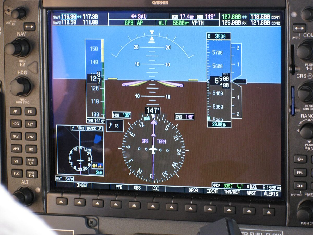
Failure shows as a warning flag, or a red cross on an electronic display, on the affected indications, a light on the warning panel, and a comparator warning if the captain's and first officer's data disagree beyond a tolerance. On a light aircraft glass cockpit an ADC failure removes the speed, altitude and vertical speed tapes but leaves attitude and heading, which come from a separate attitude and heading reference system.
Pressure transducers
A pressure transducer converts a pressure into an electrical signal. In the classic analogue ADC the transducer is typically a capsule, like that of a pneumatic instrument, whose movement is sensed by an electrical pick-off and followed by a servo loop. Solid-state transducers do without the moving linkage altogether. Whatever the technology, the aim is the same: a precise, repeatable signal free of the friction and lag of a mechanical linkage.
Many airliners place the transducers close to the probes. The Airbus A320 uses eight air data modules (ADMs) that convert the pneumatic pressures from its pitot probes and static ports into numerical data for the ADIRUs, and the Boeing 737 NG does the same for the captain's and first officer's systems. Short pneumatic lines mean less lag.
Static source error correction
A static port never senses exactly the pressure of the undisturbed air: the airframe disturbs the flow around it, by an amount that depends mainly on Mach number and angle of attack. The ADC removes this position error with a static source error correction (SSEC), sometimes called position error correction. The correction is computed in the Mach module from the aircraft-specific coefficients held in the configuration module, and applied to both the altitude and the airspeed channels before the data are output. Keeping the residual error small matters most on aircraft approved for reduced vertical separation minima (RVSM), where the total altimetry system error must be kept small. Standby instruments do not necessarily reach that standard: the Boeing 737's standby altimeter, for example, does not meet RVSM accuracy requirements. See the pitot-static system for where position error comes from and the certification limits on it.
ADIRS and ADIRU integration
Modern airliners combine air data and inertial reference into an air data and inertial reference system (ADIRS). Each air data inertial reference unit (ADIRU) has an air data reference (ADR) part and an inertial reference (IR) part, and either can work if the other fails. Putting them together suits both halves: the IR needs true airspeed for the wind and barometric altitude for its vertical channel, while the ADR's errors stay the same size over time, unlike inertial errors, which grow (see inertial navigation).

The A320 is a typical example. Its three identical ADIRUs are fed by three pitot probes, six static ports, three angle-of-attack sensors and two TAT probes, all electrically heated. ADIRU 1 takes the captain's probes, ADIRU 2 the first officer's, and ADIRU 3 the standby probes and the captain's TAT probe. The ADR part supplies barometric altitude, airspeed, Mach number, angle of attack, temperature and overspeed warnings; the IR part supplies attitude, flight path vector, heading, track, accelerations, angular rates, ground speed and position. Their users include the displays, the flight management and guidance computers, the flight control computers, the transponder and the brake and steering control unit. Normally ADIRU 1 feeds the captain's side and ADIRU 2 the first officer's; a switching selector lets ADIRU 3 replace either.
That architecture shapes the response to bad air data. The A320's unreliable speed procedure has the crew switch off the ADR parts of affected units; above FL250, if the faulty ones cannot be identified, one ADR is kept on so that the flight control computers do not act on two agreeing but wrong sources. On aircraft fitted with it, switching all three ADRs off brings up the backup speed scale, based on angle of attack, and GPS altitude replaces barometric altitude. See unreliable airspeed and the A320 ADIRS.
SAT, TAT and ram rise
Static air temperature (SAT) is the temperature of the undisturbed air through which the aircraft is flying. It is the outside air temperature (OAT) needed for true airspeed, density altitude, performance and the ISA deviation used in fuel predictions, and it is also called corrected outside air temperature (COAT).
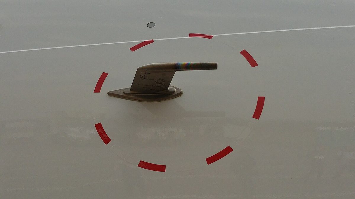
SAT cannot be measured directly at speed. Air brought to rest in a probe is heated, mainly by adiabatic compression with a small contribution from friction: the ram rise. Total air temperature (TAT) is the temperature the air would reach if brought to rest adiabatically, SAT plus the full ram rise. Below about M 0.2 the difference is small, but at airliner cruise speeds it is large. In kelvin:
TAT = SAT × (1 + 0.2 × Kr × M²), and so SAT = TAT ÷ (1 + 0.2 × Kr × M²)
where M is the Mach number and Kr the probe's recovery factor; with Kr = 1 the first formula gives the full theoretical TAT, and with the probe's real Kr the temperature it indicates. For example, with an indicated TAT of −20 °C (253 K), Kr = 0.98 and M 0.73, SAT = 253 ÷ 1.104 = 229 K, about −44 °C. At M 0.85 at FL350 in ISA, where SAT is about −54 °C, a probe with Kr = 0.98 reads about 31 °C higher. The ADC performs this calculation continuously and displays both temperatures.
Exam tip: a quick approximation quoted in ATPL texts gives ram rise in °C as (TAS ÷ 100)², with TAS in knots: 9 °C at 300 kt, 16 °C at 400 kt. It gives noticeably less than the formula above: at M 0.85 at FL350, about 490 kt TAS, it gives 24 °C against about 31 °C. Treat it as a rough cross-check, and always convert to kelvin before using the formula.
Both temperatures are used operationally. On the A320, for example, icing conditions in flight are defined by TAT, at or below +10 °C with visible moisture, while the exemption from engine anti-ice in the climb and cruise applies when SAT is below −40 °C.
Recovery factor and TAT probes
The recovery factor (Kr) is the fraction of the theoretical ram rise that a probe actually senses. No probe brings the air perfectly to rest without heat loss, so Kr is less than 1; modern TAT probes achieve about 0.95 to 0.98, a figure established by flight test. With Kr = 0.80, for comparison, a probe would read SAT plus 80 per cent of the ram rise. The temperature a probe actually measures, SAT plus the measured ram rise, is sometimes called ram air temperature; many aircraft label it TAT.
A modern TAT probe uses a platinum resistance element, whose resistance changes predictably with temperature and responds quickly. The airflow inside the probe turns through 90° before reaching the element, so that water droplets and ice particles, heavier than the air, are thrown outwards instead of wetting the sensor and cooling it by evaporation. The probe is electrically heated against ice; the heater is designed to affect the reading as little as possible, leaving an error of about 1 °C. On the A320 the TAT probes are heated in flight only, so that ground temperature indications stay accurate.
Thermocouples and bimetallic thermometers
Light aircraft often use a direct-reading bimetallic thermometer. A strip of invar, which barely expands with temperature, is bonded to brass, which expands considerably, and wound into a helix; as the temperature changes the helix twists and turns a pointer. The probe sticks through the windscreen into the airflow. At light aircraft speeds, below about M 0.2, the ram rise is small, and the reading is close to SAT. The instrument gives no electrical output.
A thermocouple is the usual sensor for high temperatures such as exhaust gas temperature. Two dissimilar metals, typically chromel and alumel, are joined at a hot junction; a voltage proportional to the difference in temperature between the hot and cold junctions appears across them. This Seebeck effect means the thermocouple generates its own signal and needs no power supply. Several probes wired in parallel give an average, so the failure of one causes only a slight drop in the indication (see engine indications).
Frequently asked questions
What does an air data computer do?
An air data computer takes pitot pressure, static pressure and total air temperature, and often angle of attack, and computes pressure altitude, calibrated airspeed, Mach number, vertical speed, true airspeed and static air temperature. It corrects them for known errors such as static source position error, and sends them to the flight displays, autopilot, flight management system, transponder, flight data recorder and warning systems.
What is the difference between static air temperature and total air temperature?
Static air temperature (SAT) is the temperature of the undisturbed air the aircraft is flying through, the value needed for true airspeed, density and performance. Total air temperature (TAT) is the higher temperature the air reaches when it is brought to rest adiabatically in a probe. The difference is the ram rise, which is negligible at low speed but amounts to about 30 °C at airliner cruise Mach numbers.
How do you calculate static air temperature from TAT?
Use SAT = TAT / (1 + 0.2 × Kr × M²), with temperatures in kelvin, where Kr is the probe's recovery factor and M the Mach number. For example, with a TAT of −20 °C (253 K), a recovery factor of 0.98 and M 0.73, SAT is about 229 K, or −44 °C. Air data computers perform this calculation continuously and display both values.
What is the recovery factor of a TAT probe?
The recovery factor, Kr, is the fraction of the theoretical ram rise that a temperature probe actually senses. No probe brings the air perfectly to rest without losing heat, so Kr is less than 1. Modern TAT probes achieve about 0.95 to 0.98. The value is found by flight test and used in the formula that converts the measured temperature to static air temperature.
What is an ADIRU?
An air data inertial reference unit (ADIRU) combines an air data computer and an inertial reference system in one box. On the A320 each of the three ADIRUs has an air data reference part, supplying altitude, airspeed, Mach number, angle of attack and temperature, and an inertial reference part, supplying attitude, heading, track, ground speed and position. Either part can keep working if the other fails.
Test yourself on Air Data Computer and Air Temperature
The v1prep banks cover this topic in Instrumentation (022), with a worked explanation for every answer. EASA ATPL, PPL, IR and CPL, the FAA written tests and A320/B737 type ratings.
Start practising →Sources and further reading
- FAA Pilot's Handbook of Aeronautical Knowledge (FAA-H-8083-25), Chapter 8, Flight Instruments
- FAA Instrument Flying Handbook (FAA-H-8083-15B), Chapter 5, Flight Instruments
- 14 CFR 25.1325, Static pressure systems
- FAA, Design for RVSM Compliance, RSSE and 3σ Error Evaluation
- EASA Easy Access Rules for Large Aeroplanes (CS-25)
- EASA, Explanatory Note to ED Decision 2018/001/R, Part-FCL theoretical knowledge learning objectives (022 Instrumentation)
Library articles are written for study and exam preparation. They do not replace your aircraft's approved documentation, your operator's procedures or the regulations themselves.