Airspeed Indicator and Machmeter
The airspeed indicator (ASI) is a differential pressure gauge that measures dynamic pressure, pitot minus static, and displays it as indicated airspeed calibrated for sea-level standard density. The Machmeter uses the same two pressures to show Mach number, the ratio of true airspeed to the local speed of sound.
The airspeed indicator (ASI) does not measure speed directly. It measures dynamic pressure, the pressure that the aircraft's motion adds to the ambient air, and shows it on a scale graduated in knots. Because dynamic pressure is also what the wing and the structure respond to, indicated airspeed is the speed a pilot flies: stall speeds, flap limits and rotation speeds are all published as indicated or calibrated airspeeds.
The Machmeter takes the same two pressures and shows Mach number, which becomes the limiting speed of a jet at high altitude. On airliners both are usually combined in one instrument or shown on the speed tape of the primary flight display, with the pressures converted by an air data computer.
How the ASI works
The ASI is a differential pressure gauge. A thin corrugated metal capsule inside the instrument receives pitot pressure, which is static plus dynamic pressure. The sealed case around the capsule receives static pressure. Static pressure acts on both sides of the capsule wall and cancels, so the capsule expands and contracts with dynamic pressure alone. A linkage and gear train turn that movement into pointer movement. How the pressures reach the instrument, and what blockages do to it, is covered under the pitot-static system.
Dynamic pressure is ½ρV², so the reading depends on air density as well as speed. The instrument is calibrated for the density of the International Standard Atmosphere at mean sea level, 1.225 kg/m³ (1013.25 hPa and +15 °C). Only in those conditions does it show the true speed through the air; everywhere else it shows indicated airspeed (IAS), written KIAS when expressed in knots. Because the capsule responds to the square of speed, the scale is non-linear: the low-speed end is compressed and the high-speed end spread out, which makes an analogue ASI hardest to read precisely at low speed.

ASI colour markings and arcs
The ASI of a light aeroplane carries standard colour markings. EASA and FAA material describe the same scheme, following the general instrument code of green for normal, yellow or amber for caution and red for limits.
| Marking | From | To | Meaning |
|---|---|---|---|
| White arc | VS0 | VFE | Flap operating range |
| Green arc | VS1 | VNO | Normal operating range |
| Yellow arc | VNO | VNE | Caution range, smooth air only |
| Red radial line | VNE | Never exceed speed | |
| Red radial line (light twins) | VMCA | Minimum control speed, critical engine inoperative | |
| Blue radial line (light twins) | VYSE | Best rate of climb, one engine inoperative |
The lower end of the white arc (flap operating range) is VS0, the stalling speed in the landing configuration at maximum weight; its upper end is VFE, the maximum flap extended speed. The lower end of the green arc is VS1, the stalling speed in a specified configuration, normally clean. VNO is the maximum structural cruising speed: above it a strong gust could overstress the aeroplane, hence the smooth-air restriction on the yellow arc. VNE is set no higher than 0.9 of the design dive speed, leaving a margin against flutter and structural failure. The blue line, VYSE, is the speed to fly after an engine failure in a light twin (see minimum control speeds).
Several important speeds are not painted on the dial. The manoeuvring speed VA falls as weight decreases, so it is placarded or taken from the flight manual; VLE, VLO, VX and VY are also found only in the handbook.
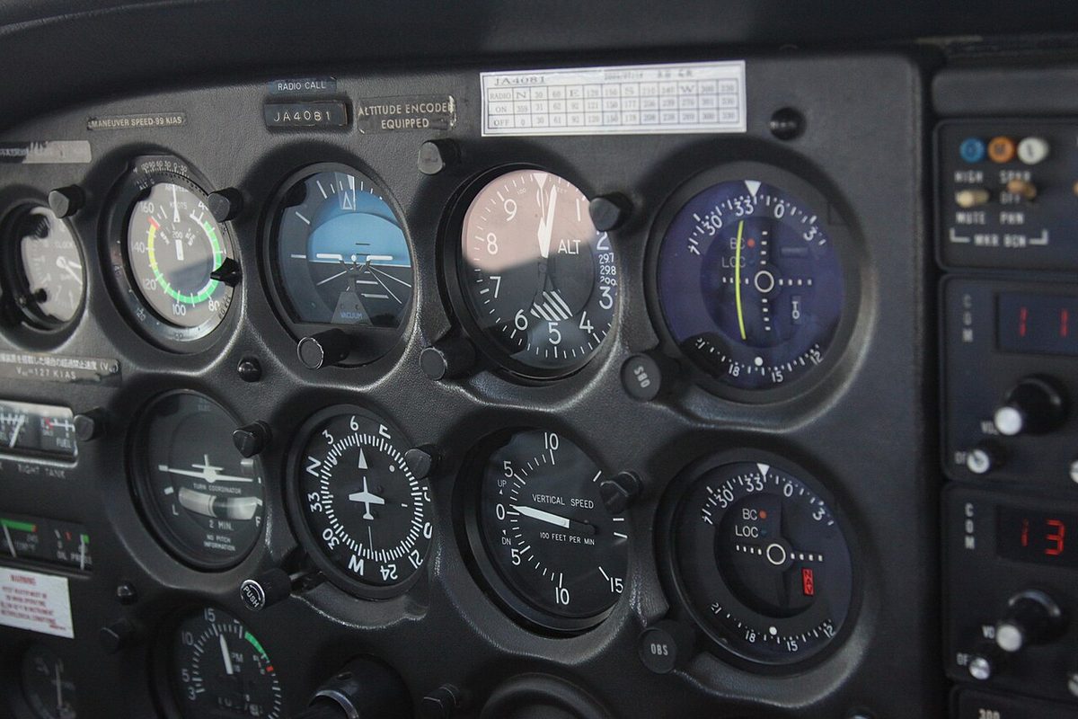
Exam tip: stalling speeds are shown by the lower ends of the white and green arcs, never by a radial line. A red radial line at the low-speed end of a light twin's ASI is VMCA.
The ASIs of transport jets carry no arcs. Their limits are shown by moving pointers and bars positioned continuously from air data, described below.
Airspeed and speed bugs
A speed bug or airspeed bug is a movable marker set against the airspeed scale to remind the crew of a target or reference speed. On a round-dial instrument the bugs are cursors round the bezel, set by hand to V1, VR, V2 or the reference landing speed.
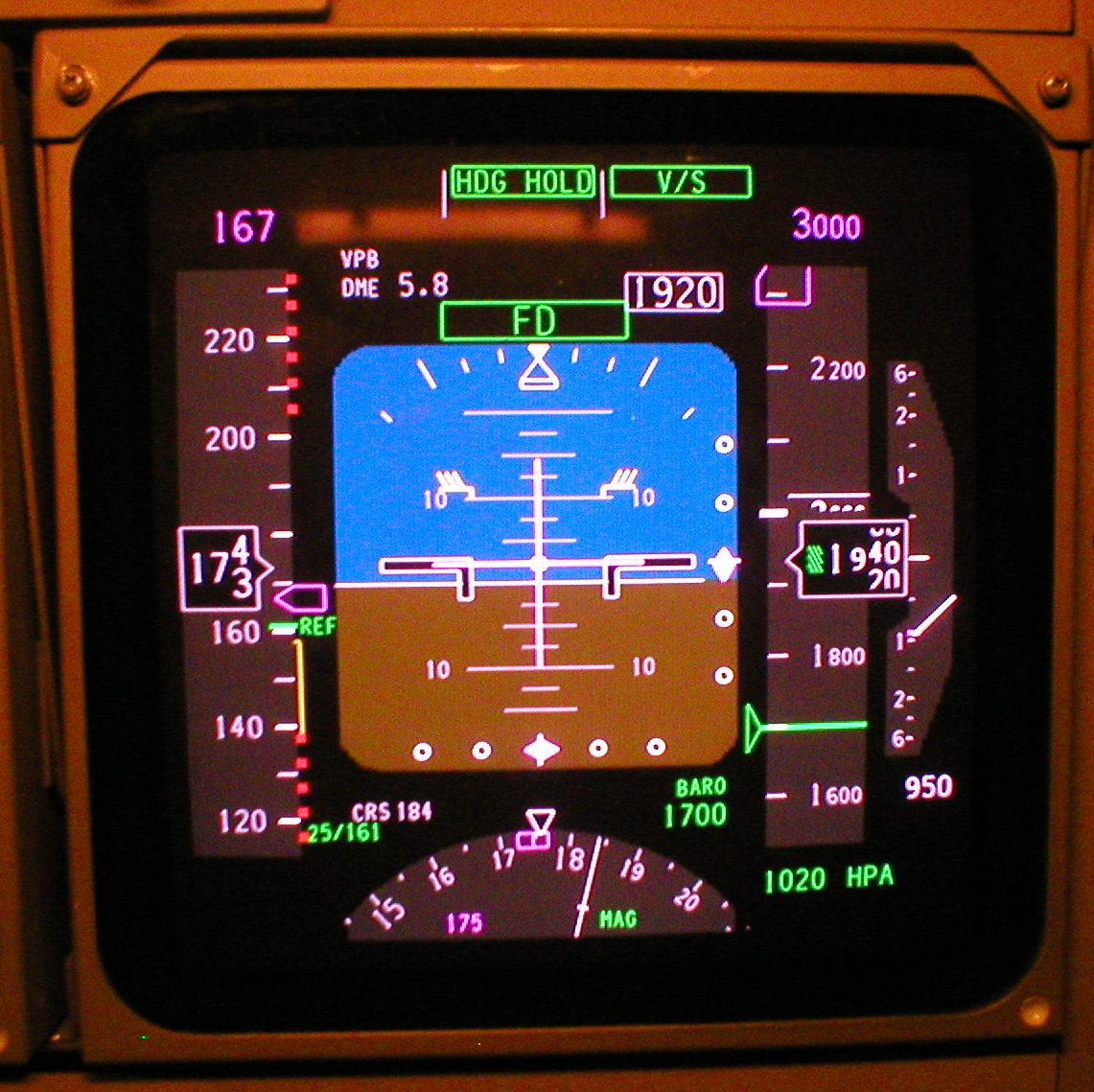
On an electronic speed tape the display system draws the bugs. On the Boeing 737 a magenta bug shows the speed selected on the mode control panel or computed by the flight management computer. V1 and VR are shown for take-off, with an amber NO VSPD flag if they have not been entered, and green bugs mark the flap manoeuvring speeds. A green arrow, the speed trend vector, points to the speed predicted 10 seconds ahead. The A320's standby instrument has a bugs function too, but Airbus recommends against using it: take-off bugs left in place would still be shown during the approach if both primary displays failed. See take-off speeds for what the reference speeds mean.
IAS, CAS, EAS and TAS
Indicated airspeed is converted to true airspeed by removing errors in a fixed order:
| Speed | Obtained from | By correcting for |
|---|---|---|
| Indicated airspeed (IAS) | The instrument reading | |
| Calibrated airspeed (CAS) | IAS | Instrument and position error |
| Equivalent airspeed (EAS) | CAS | Compressibility error |
| True airspeed (TAS) | EAS | Density error |
Calibrated airspeed (CAS), called rectified airspeed in older British texts, is IAS corrected for instrument and position errors; in a light aeroplane both are covered by the airspeed calibration table in the handbook. Equivalent airspeed (EAS) is CAS corrected for compressibility and is the true measure of dynamic pressure. True airspeed (TAS) is the actual speed of the aircraft through the air mass: TAS = EAS × √(ρ0/ρ), where ρ0 is ISA sea-level density and ρ the actual density. Air data computers apply these corrections automatically.
Because lift depends on dynamic pressure, an aeroplane of a given weight stalls, and lifts off, at the same EAS at any altitude; at low speed that is also, very nearly, the same IAS. The TAS needed rises as density falls, which is why take-off runs are longer at a hot or high aerodrome. A common rule of thumb adds about 2 per cent to the indicated speed for every 1,000 ft, so 100 KIAS at 6,000 ft is roughly 112 kt TAS. A flight computer using pressure altitude and temperature gives the exact figure.
Exam tip: in a climb at constant CAS, TAS rises and Mach number rises faster still. Climbing from sea level to FL360 at 330 kt CAS in ISA, TAS increases from 330 to about 555 kt and Mach number from 0.50 to about 0.97.
Instrument, compressibility and density errors
Instrument error comes from the construction of the instrument itself: manufacturing tolerances in the capsule, friction in the linkage and backlash in the gears. Position error, also called pressure error, arises because the static port and, to a lesser extent, the pitot probe sense a pressure disturbed by the airframe. It is greatest at high angles of attack, close to the stall, and small in the cruise. For transport aircraft, 14 CFR 25.1323 and its CS-25 equivalent limit the installation error to 3 per cent or 5 kt, whichever is greater. Manoeuvre-induced error is the brief false reading caused by pressure changes at the static vents during rapid attitude changes.
Compressibility error appears at high speed and altitude. Air brought to rest in the pitot probe is compressed, so the pressure it senses exceeds ½ρV². The calibration allows for this compression only as it occurs at sea level in ISA: the FAA's definition of indicated airspeed in 14 CFR 1.1 refers to compressible flow at standard sea level. Higher up, the same dynamic pressure corresponds to a higher Mach number and more compression, so the ASI over-reads and the correction from CAS to EAS is subtracted. ATPL texts treat the error as negligible below about 300 kt TAS; it grows with speed and altitude and can exceed 20 kt close to the speed of sound. For most light aircraft CAS and EAS can be treated as equal.
Density error is the difference between EAS and TAS. Whenever the air is less dense than ISA sea-level air, as it is at height or on a warm day, the ASI under-reads TAS. The correction needs pressure altitude and outside air temperature, which is why an air data computer needs a temperature probe to compute TAS.
The Machmeter
Mach number is TAS divided by the local speed of sound (LSS). The LSS depends only on absolute temperature, about 38.95 × √T knots with T in kelvin: roughly 661 kt at ISA mean sea level and 573 kt at and above the ISA tropopause (see high-speed flight).
Mach number is fixed by the ratio of dynamic pressure to static pressure. A mechanical Machmeter therefore contains an airspeed capsule, fed with pitot pressure inside a case at static pressure, and an altitude capsule, an evacuated aneroid that expands as static pressure falls. A ratio arm combines the two movements to drive the pointer. Because the pressure ratio fixes Mach number directly, whatever the air density, the Machmeter needs no temperature input and has no density or compressibility error. It suffers only instrument, position and manoeuvre-induced errors.
The raw Machmeter reading corrected for instrument error is the indicated Mach number (IMN), the figure normally used in flight manuals; corrected also for position error it becomes the true Mach number (TMN). ATPL texts add that on jet transports the residual position error is arranged so that the Machmeter over-reads, erring towards slowing down before MMO. Blockages affect it in the same sense as the ASI: with a blocked static source it under-reads in a climb, with a blocked pitot it over-reads in a climb.
| Climb at constant | TAS | Mach number | CAS |
|---|---|---|---|
| CAS, troposphere | Increases | Increases | Constant |
| Mach, troposphere | Decreases | Constant | Decreases |
| Mach, isothermal layer | Constant | Constant | Decreases |
On a combined Mach/airspeed indicator, a single pointer moves over a fixed scale in knots while a Mach scale, usually starting at M 0.5, is turned anticlockwise beneath it as the aircraft climbs, so the same pointer reads both. Electronic displays show Mach as a digital readout once it exceeds a set value, M 0.40 on the Boeing 737 PFD and M 0.5 on the A320's standby instrument. For transport aeroplanes, 14 CFR 25.1303 and CS 25.1303 require a Machmeter at each pilot station when compressibility limitations are not otherwise shown by the airspeed indicating system.
Barber pole and overspeed warning
A jet has two maximum operating speeds: VMO, an indicated airspeed set by dynamic pressure limits such as structural and gust loads lower down, and MMO, a Mach number that protects against the effects of shock waves higher up. Climbing at constant IAS raises the Mach number, so above a crossover altitude MMO becomes the limit first. For the A320 family, with VMO 350 kt and MMO M 0.82, the two meet in ISA at about FL245; ATPL texts put the changeover for jet transports generally between about FL240 and FL290.
On a round-dial ASI the maximum operating speed is shown by a red and white striped pointer, the barber pole or barber's pole. Below the crossover altitude it stays at VMO. Above it, MMO corresponds to an ever lower indicated airspeed as the aircraft climbs, so the pointer moves anticlockwise, down the scale. On a speed tape the same function is a red and black bar. On the Boeing 737 its lower end shows the lowest of VMO or MMO, the landing gear placard speed and the flap placard speed, and, with flaps up, an amber bar below it marks the maximum manoeuvring speed that still gives 1.3 g to high-speed buffet. The A320 shows VMAX as a red and black strip.
The overspeed warning does not rely on the crew noticing the display. CS 25.1303(c)(1) and 14 CFR 25.1303(c)(1), which are harmonised, require an aural warning whenever the speed exceeds VMO + 6 kt or MMO + 0.01; the A320's ECAM warning comes earlier, at VMO + 4 kt or MMO + 0.006. The Boeing 737 sounds a clacker that can be silenced only by reducing speed below VMO/MMO; on the A320 the master warning pushbutton does not cancel the overspeed aural. On the A320 the VMAX strip follows the flap lever position while the warning uses the actual surface position, so a brief warning during flap retraction can occur without the speed entering the strip.
Warning: below MMO is not the same as below buffet onset. At high altitude, weight and bank angle, high-speed buffet can occur below MMO; see high-speed flight and structural and operating speed limits.
Recovery from an overspeed uses reduced thrust, the speedbrakes and a gentle pitch change, avoiding large control inputs at high dynamic pressure. Fly-by-wire aircraft add high-speed protection in their control laws (see fly-by-wire). If the airspeed and Mach indications themselves become doubtful, the crew applies the unreliable airspeed procedure.
Frequently asked questions
What is the difference between IAS, CAS, EAS and TAS?
Indicated airspeed (IAS) is what the instrument shows. Corrected for instrument and position error it becomes calibrated airspeed (CAS). Corrected for compressibility, which matters only at high speed and altitude, CAS becomes equivalent airspeed (EAS), a true measure of dynamic pressure. Corrected for air density, EAS becomes true airspeed (TAS), the real speed through the air, which is higher than the others whenever the air is less dense than at sea level in ISA.
What do the colour arcs on an airspeed indicator mean?
The white arc is the flap operating range, from VS0, the stall speed in landing configuration at maximum weight, up to VFE. The green arc is the normal operating range from VS1 to VNO. The yellow arc, from VNO to VNE, may be used only in smooth air. The red radial line is VNE. Light twins add a red radial line for VMCA and a blue one for VYSE, the best single-engine rate-of-climb speed.
Why does true airspeed increase with altitude at the same indicated airspeed?
The airspeed indicator measures dynamic pressure, which depends on air density as well as speed. As density falls with height, the aircraft must move faster through the air to produce the same dynamic pressure, so the same indicated airspeed means a higher true airspeed. A common rule of thumb adds about 2 per cent per 1,000 ft, so 120 kt indicated at 10,000 ft is roughly 144 kt true.
Why is the Machmeter free from density and compressibility errors?
Mach number depends only on the ratio of dynamic pressure to static pressure, and the Machmeter measures exactly that ratio with an airspeed capsule and an altitude capsule. The ratio gives Mach number directly whatever the air density, and compressibility is already part of that relationship, so no temperature input or density correction is needed. The Machmeter still suffers instrument, position and manoeuvre-induced errors.
What is the barber pole on an airspeed indicator?
The barber pole is the red and white striped pointer or bar that shows the maximum operating speed of a jet. Below the crossover altitude it shows VMO as a constant indicated airspeed. Higher up, MMO becomes the limit, and because a fixed Mach number corresponds to a lower indicated airspeed as the aircraft climbs, the barber pole moves down the scale. Exceeding it triggers the overspeed warning.
Test yourself on Airspeed Indicator and Machmeter
The v1prep banks cover this topic in Instrumentation (022), with a worked explanation for every answer. EASA ATPL, PPL, IR and CPL, the FAA written tests and A320/B737 type ratings.
Start practising →Sources and further reading
- FAA Pilot's Handbook of Aeronautical Knowledge (FAA-H-8083-25), Chapter 8, Flight Instruments
- FAA Instrument Flying Handbook (FAA-H-8083-15B), Chapter 5, Flight Instruments
- 14 CFR 1.1, General definitions (indicated airspeed, calibrated airspeed, true airspeed)
- 14 CFR 25.1303, Flight and navigation instruments (speed warning device, Machmeter)
- 14 CFR 25.1323, Airspeed indicating system
- EASA Easy Access Rules for Large Aeroplanes (CS-25)
- EASA, Explanatory Note to ED Decision 2018/001/R, Part-FCL theoretical knowledge learning objectives (022 Instrumentation)
Library articles are written for study and exam preparation. They do not replace your aircraft's approved documentation, your operator's procedures or the regulations themselves.