Pitot-Static System
The pitot-static system senses total (pitot) pressure and static pressure outside the aircraft and delivers them to the airspeed indicator, altimeter, vertical speed indicator and Machmeter, or to air data computers that derive the same quantities electronically.
The pitot-static system is the set of probes, ports and pipes that measures the pressure of the air around an aircraft. It senses two pressures: total pressure, also called pitot pressure, from a forward-facing probe, and static pressure, the ambient pressure of the undisturbed air, from openings in the side of the fuselage. Indicated airspeed, altitude, vertical speed and Mach number all come from those two pressures.
On a light aircraft the pressures travel through tubing straight to capsule instruments on the panel. On an airliner they are converted to electrical signals and processed by air data computers, whose outputs also feed the autopilot, autothrust, transponder, pressurisation controller and warning systems. The physics is the same in both. This article describes the hardware, its protection and its built-in errors; how crews recognise and handle corrupted air data in flight is covered in unreliable airspeed.
How pitot and static pressures reach the instruments
Air brought to rest in the probe's open end adds its dynamic pressure to the static pressure already present, so pitot pressure is the sum of the two. The airspeed indicator subtracts static pressure from pitot pressure and displays the difference, dynamic pressure, as indicated airspeed. The altimeter and the vertical speed indicator (VSI) use static pressure alone. The altimeter converts it to a height in the standard atmosphere (see altimeter settings); the VSI compares it with the pressure inside its case, which follows only slowly through a calibrated leak. The Machmeter uses both, because Mach number depends on the ratio of dynamic to static pressure.
| Instrument | Pitot pressure | Static pressure |
|---|---|---|
| Airspeed indicator | Yes | Yes |
| Machmeter | Yes | Yes |
| Altimeter | No | Yes |
| Vertical speed indicator | No | Yes |
Transport aircraft carry at least two independent systems, one for each pilot, plus a separate supply for the standby instruments. The Boeing 737 NG is typical. It has three pitot probes: the captain's on the left side, and the first officer's and an auxiliary pitot probe on the right. It has six flush static ports: a captain's, a first officer's and an alternate port on each side. Air data modules convert the captain's and first officer's pressures into electrical signals for the air data inertial reference units. The auxiliary probe and the alternate static ports supply the standby airspeed indicator and altimeter directly, and the alternate ports also feed the cabin differential pressure indicator. An auxiliary probe is an extra pitot source, independent of the main systems, so that one blocked or iced probe cannot take every airspeed indication with it (see air data computer).

Pitot probes and heads
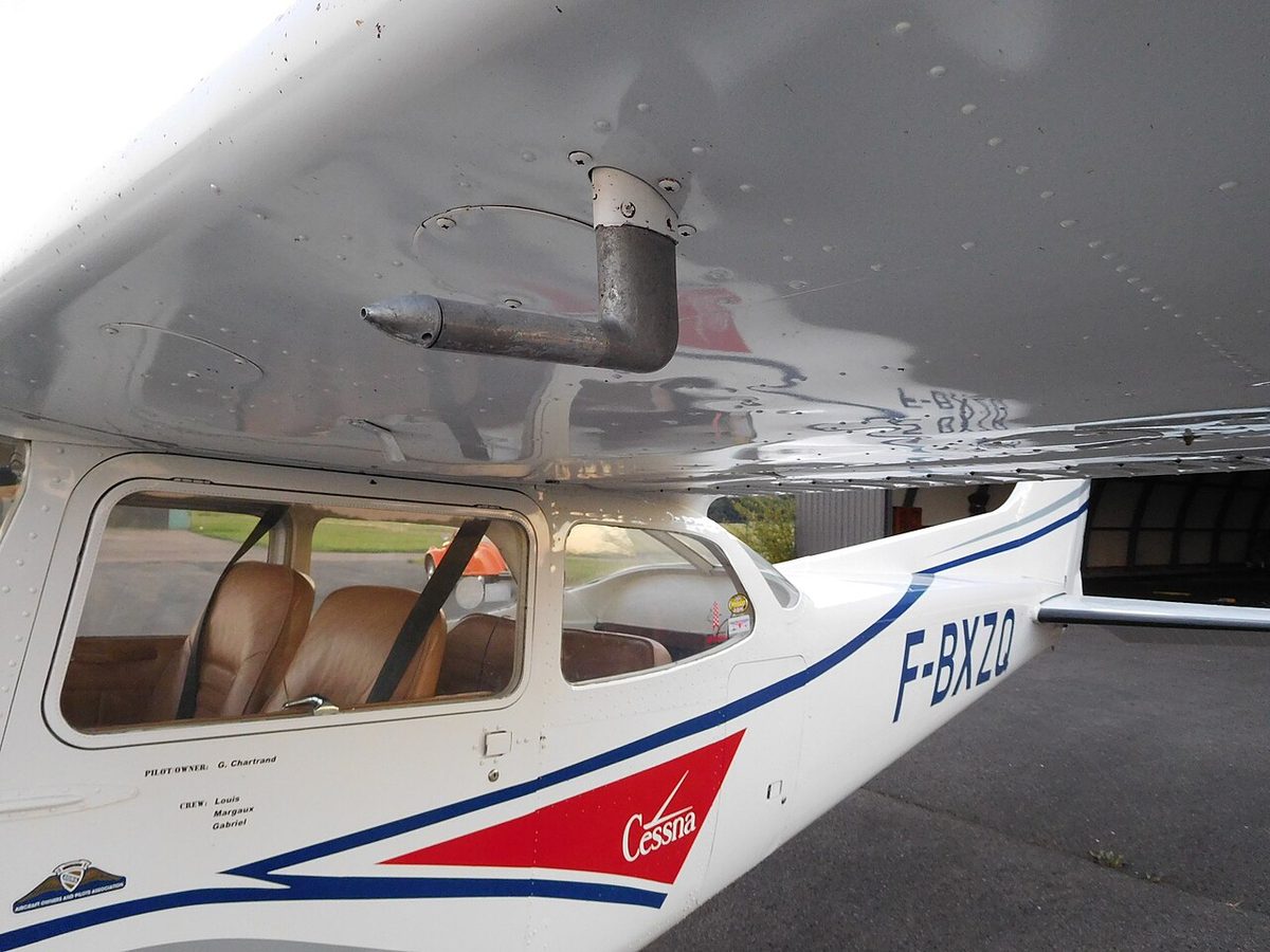
The pitot probe, also called the pitot tube or pitot head, is an open tube pointing forward, parallel to the airflow, mounted where the airframe disturbs the air least: under a wing on many light aircraft, on the sides of the nose on airliners, sometimes on a short mast that holds it clear of the skin. Some types use a combined pitot-static head, with static holes around the barrel behind the inlet.
A small drain hole near the front of the probe lets rain and condensation run out. It leaks a little pressure, but the leak is small compared with the flow into the inlet and is allowed for in calibration. It matters when the inlet blocks. With the drain open, the pressure in the line bleeds away to static and the airspeed falls towards zero; with both inlet and drain blocked, the pressure is trapped.
Probe heating keeps ice out. Electric elements inside the probe are switched on by the crew or automatically, and a caution warns when heat is off or has failed. The transport category airworthiness standards require each airspeed system to have a heated pitot tube or an equivalent means of preventing malfunction due to icing. Angle-of-attack vanes and total air temperature probes, which sit in the same exposed airflow, are heated for the same reason. Heat defends against ice, not against insects, dust or a cover left in place; those are found only on a careful walk-round (see airframe icing).
Static ports and vents
A static port, or static vent, is a small hole or group of holes in a flush plate on the side of the fuselage, opening at right angles to the airflow. The designer places it where, by flight test, the local pressure stays closest to ambient across the speed range and configurations. The reading depends on smooth flow over the plate, so dents, paint, sealant or damaged skin near the port all introduce error. Ports are therefore marked, kept clean and inspected.
On most larger aircraft the ports are fitted in pairs, one on each side of the fuselage, and joined into a common line: cross-coupled static vents. In a sideslip, air is pushed against the port on the windward side, raising its pressure, while the port on the leeward side sees a lower pressure. Joined together, the two errors largely cancel. An aircraft with a single static port, common on older light aircraft, can show a noticeable airspeed error in a slip.
In a pressurised aircraft the static lines run inside the pressure hull. A cracked or disconnected line there admits cabin air, which at altitude is at a higher pressure than the air outside. The altimeter then reads close to the cabin altitude and the airspeed indicator under-reads, which is one reason the system is leak-tested whenever it has been disturbed.
Alternate static source
The alternate static source is a second static supply for use when the normal ports are blocked, typically by ice. In an unpressurised light aircraft it is a valve or knob, usually under the instrument panel, that opens the static line to the cabin. Air flowing past the fuselage and its openings keeps cabin pressure slightly below ambient, so on selecting it the altimeter reads a little high, the airspeed indicator shows more than the actual speed and the VSI shows a momentary climb before settling. The pilot's operating handbook may give corrections and specify vent or heater settings to use with it.
A pressurised aircraft cannot vent its alternate source to the cabin, whose pressure bears no fixed relation to ambient at altitude. Its alternate ports are on the outside skin, like the 737 NG ports that feed the standby instruments. On aircraft with air data computers the equivalent action is usually electrical: the crew switches the affected displays to another air data source.
Drains and water traps
Water enters the lines as rain, washing water or condensation and runs to the lowest point. Lines are routed to fall towards drain fittings at those low points, forming a pitot-static water trap, or sump, where the water collects instead of reaching the instruments. On the 737 NG each pitot and static line has a drain fitting with a transparent section and a float that shows how much water has gathered. Drains are emptied by maintenance staff on the ground.
Water left in a line causes erratic or intermittent indications and, if it freezes at altitude, a blockage as complete as ice in the probe. Probe heat alone therefore does not guarantee clear lines.
The United States writes a periodic check into its operating rules. Under 14 CFR 91.411, an aeroplane or helicopter may fly IFR in controlled airspace only if each static pressure system, altimeter and automatic pressure altitude reporting system has been tested and inspected within the preceding 24 calendar months. The static system must also be retested after it has been opened and closed, unless the only work was using the system drains or the alternate static valve. European operators and owners follow the checks in each aircraft's approved maintenance programme.
Blockage effects in summary
A pitot blockage, also called a pitot probe blockage or pitot tube blockage, affects only the instruments that use pitot pressure. A static blockage, or static port blockage, affects every instrument on that static line. A pitot-static blockage, with both sources blocked, freezes the pressure instruments. The table gives the effects in a climb or descent. In level flight at constant speed a trapped pressure shows nothing wrong until speed or altitude changes.
| Fault | Airspeed indicator | Altimeter | VSI | Machmeter |
|---|---|---|---|---|
| Pitot inlet blocked, drain open | Falls towards zero | Correct | Correct | Falls towards zero |
| Pitot inlet and drain blocked | Over-reads in a climb, under-reads in a descent | Correct | Correct | Over-reads in a climb, under-reads in a descent |
| Static blocked, pitot clear | Under-reads in a climb, over-reads in a descent | Frozen | Zero | Under-reads in a climb, over-reads in a descent |
| Pitot and static both blocked | Frozen | Frozen | Zero | Frozen |
| Alternate static in the cabin, unpressurised | Slightly high | Slightly high | Brief climb, then correct | Slightly high |
| Static line leaking into a pressurised cabin | Under-reads | Near cabin altitude | Shows cabin rate | Under-reads |
Pitot under-reads in descent, static over-reads in descent (PUDSOD) is the mnemonic for the two cases examiners ask most; reverse both for a climb. The static case is the more hazardous, because in a descent the aircraft is slower than indicated. Recognition, memory items and the accidents behind them are in unreliable airspeed.
Position error and position error correction
Position error, also called pressure error or installation error, is the difference between the pressure a probe or port actually senses and the true pitot or ambient pressure, caused by the airframe disturbing the flow around it. It is mostly a static port problem. A pitot probe facing into the flow tolerates small changes of angle, while the pressure at a static port shifts whenever the flow pattern around the fuselage changes. The error varies with airspeed, angle of attack, flap and landing gear configuration, sideslip and, on fast aircraft, Mach number. Near the ground the flow changes again: the FAA notes that in most installations ground effect raises the pressure at the static source, so airspeed and altitude read slightly low.
Indicated airspeed corrected for instrument error and position error is calibrated airspeed (CAS). The position error correction (PEC) is the correction that removes the position error, determined by flight test against a calibrated reference. Light aircraft handbooks publish it as an airspeed calibration table or graph, sometimes with a separate table for the alternate static source. Air data computers apply it automatically as a static source error correction (SSEC), based at least on Mach number and often on angle of attack as well. SSEC is standard on transonic aircraft approved for reduced vertical separation minima (RVSM), where the total altimetry system error has to be kept small.
Certification sets limits. For transport aeroplanes, 14 CFR 25.1323, mirrored in CS-25, allows an airspeed error of the installation, excluding the indicator's own calibration error, of no more than 3% or 5 kt, whichever is greater, over the specified speed ranges. Paragraph 25.1325 limits the resulting altitude error to ±30 ft per 100 kt of speed between 1.23 VSR0 with flaps extended and 1.7 VSR1 with flaps retracted. EASA and UK texts mostly say position or pressure error; FAA handbooks also say installation error. At high speed the correction chain continues from CAS to equivalent airspeed by removing compressibility error (see high-speed flight).
Lag and manoeuvre-induced error
Pressure changes take time to travel along the lines and to move capsules and linkages, so every pneumatic instrument lags. In a steady climb a lagging altimeter under-reads and in a descent it over-reads; the error grows with the rate of climb or descent and with the length of the tubing. The VSI lags by design. Its needle shows the direction of a change at once, but the rate settles only after several seconds, as the pressure in its case catches up through the calibrated leak. Servo-driven altimeters, air data modules mounted close to the probes and instantaneous VSIs with an accelerometer element all reduce lag.
Manoeuvre-induced error is a brief false indication caused by pressure changes at the static vents when the airflow around the fuselage changes quickly: at rotation, in a sharp pitch change, when the gear or flaps move, at the start of a go-around and in rough air. It is greatest in pitch changes and disappears once the aircraft is steady. The practical rule follows: during a rapid manoeuvre, fly attitude and use the pressure instruments once they have settled.
Exam tip: instrument, position and manoeuvre-induced errors affect both the airspeed indicator and the Machmeter. Density and compressibility errors affect airspeed only, because they cancel in the pressure ratio the Machmeter measures.
Frequently asked questions
What instruments are connected to the pitot-static system?
The airspeed indicator and the Machmeter use both pitot and static pressure. The altimeter and the vertical speed indicator use static pressure only. On aircraft with air data computers the same pressures also feed the autopilot, autothrust, transponder altitude reporting, pressurisation controller and warning systems, so a pressure fault can reach far more than the flight instruments.
What is the drain hole in a pitot tube for?
The small hole near the front of the probe lets rain and condensation run out, so water does not collect in the line or freeze there. If ice blocks the inlet but the drain stays open, the pressure leaks away and the airspeed falls towards zero. If both are blocked, the trapped pressure makes the airspeed indicator behave like an altimeter.
What happens when you select the alternate static source?
In an unpressurised aircraft the alternate source usually vents into the cabin, where the pressure is slightly lower than outside. The altimeter then reads slightly high, the airspeed indicator shows more than the actual speed and the vertical speed indicator shows a brief climb before settling. The handbook may give corrections. Pressurised aircraft use alternate ports on the outside skin instead.
What is position error in the pitot-static system?
Position error, also called pressure or installation error, is the difference between the pressure a probe or static port senses and the true pressure, caused by the airframe disturbing the local airflow. It changes with speed, angle of attack, configuration and sideslip. Correcting indicated airspeed for it and for instrument error gives calibrated airspeed; air data computers apply the correction automatically.
Why are there static ports on both sides of the fuselage?
In a sideslip the port on the windward side senses a higher pressure and the port on the leeward side a lower one. Connecting the two into a single line, called cross-coupling, averages the pressures so that the sideslip errors largely cancel. Airliners carry several such pairs, one for each independent air data system, plus alternate ports for the standby instruments.
How often must the static system and altimeter be tested?
In the United States, 14 CFR 91.411 allows IFR flight in controlled airspace only if each static pressure system, altimeter and automatic pressure altitude reporting system has been tested and inspected within the preceding 24 calendar months. The static system must also be retested whenever it has been opened and closed, except for use of the drains or the alternate static valve.
Test yourself on Pitot-Static System
The v1prep banks cover this topic in Instrumentation (022), with a worked explanation for every answer. EASA ATPL, PPL, IR and CPL, the FAA written tests and A320/B737 type ratings.
Start practising →Sources and further reading
- FAA Pilot's Handbook of Aeronautical Knowledge (FAA-H-8083-25), Chapters 5 and 8
- 14 CFR 25.1323, Airspeed indicating system
- 14 CFR 25.1325, Static pressure systems
- 14 CFR 91.411, Altimeter system and altitude reporting equipment tests and inspections
- FAA, Design for RVSM Compliance, RSSE and 3σ Error Evaluation
Library articles are written for study and exam preparation. They do not replace your aircraft's approved documentation, your operator's procedures or the regulations themselves.