Structural Design and Design Loads
Structural design is the sizing of an aircraft's structure for the loads it will meet in service: the design limit load, carried without permanent deformation, and the design ultimate load, 1.5 times the limit load, carried without failure, with fatigue controlled by safe-life, fail-safe or damage-tolerant design.
An aircraft structure must be light enough to fly and strong enough never to fail, and structural design is the discipline that reconciles the two. The designer first establishes the design loads: the largest loads the aircraft is expected to meet in manoeuvres, gusts, landings and pressurisation, across its whole range of masses, centre of gravity positions and speeds. The structure is then sized to carry those loads with a defined margin, and to go on carrying them through years of repeated loading, corrosion and accidental damage.
Two questions run through the subject. The first is static strength: can the structure carry the design limit load without permanent deformation, and the design ultimate load without breaking? The second is durability: how is fatigue cracking prevented from ever reaching a dangerous size? The certification codes, CS-23 and CS-25 in Europe and 14 CFR Parts 23 and 25 in the United States, answer both. The pilot meets their answers as the speed, load factor and mass limitations of the flight manual.
Where Design Loads Come From
An airframe carries several kinds of load at once:
- Flight loads: the lift of the wing and the balancing load on the tail, which rise in manoeuvres and gusts. The load factor measures them (see load factor and flight envelope).
- Ground loads: landing impacts, taxiing over rough surfaces, braking and turning.
- Pressurisation loads: the cabin pressure differential stretches the fuselage around its circumference (hoop stress) and along its length (axial stress); in a cylindrical fuselage the hoop stress is about twice the axial stress.
- Inertia loads from fuel, engines, cargo and passengers. Mass carried in the wing bends it downwards, against the upward bending of lift, so wing fuel and wing-mounted engines relieve the wing root; mass in the fuselage gives no such relief, which is the reasoning behind the maximum zero fuel mass (see maximum structural and regulated masses).
Loads are also static, building slowly like the weight of a parked aeroplane, or dynamic, building quickly in manoeuvres, gusts and landings. A wing spar sees both: bent downwards by its own weight on the ground and upwards by lift in flight.
For manoeuvres the codes set limit load factors: +2.5 g and -1.0 g for a large transport aeroplane, +2.0 g with the flaps extended, and up to +3.8 g and -1.52 g for a normal category light aeroplane. For gusts, ATPL texts quote design vertical gust velocities of 66 ft/s at VB, the design speed for maximum gust intensity, 50 ft/s at VC, the design cruising speed, and 25 ft/s at VD, the design diving speed, all in equivalent airspeed. The faster the aeroplane flies, the smaller the gust it is designed to meet, which is one reason to slow to the turbulence speed in rough air.

Limit and Ultimate Loads
The design limit load (DLL) is the maximum load the aircraft is expected to meet in service. The structure must carry it without detrimental permanent deformation, and at any load up to it no deformation may interfere with safe operation. ATPL texts add that it is the maximum load that can be applied repeatedly in normal operation without inducing excessive fatigue, and that a pilot must never deliberately exceed it.
The design ultimate load (DUL) is the limit load multiplied by the factor of safety of 1.5. The structure must carry it for at least three seconds without failure. Between the two the structure may be bent or stretched permanently; beyond the ultimate load it may fail.
| Load | Definition | Requirement | Beyond it |
|---|---|---|---|
| Design limit load | Maximum load expected in service | No detrimental permanent deformation | Permanent deformation possible; inspection required |
| Design ultimate load | Limit load × 1.5 | Carried for at least 3 s without failure | Structural failure possible |
A transport aeroplane designed to a limit load factor of +2.5 g therefore has an ultimate load factor of 3.75 g, and a normal category aeroplane designed to +3.8 g one of 5.7 g.
Exam tip: limit load means no permanent deformation; ultimate load means no failure. The ultimate load is 1.5 times the limit load, and exceeding the limit load is a maintenance event even when nothing visibly breaks.
Factor of Safety
The factor of safety is the ratio of ultimate to limit load. For aircraft structure it is 1.5, in the EASA and the FAA codes alike. It exists because loads, materials and workmanship are never known exactly: a gust may be sharper than the design gust, a pilot may pull harder than intended, a batch of material may sit at the low end of its specification, and structure deteriorates with age. It is a margin for the unforeseen, not a reserve for routine use.
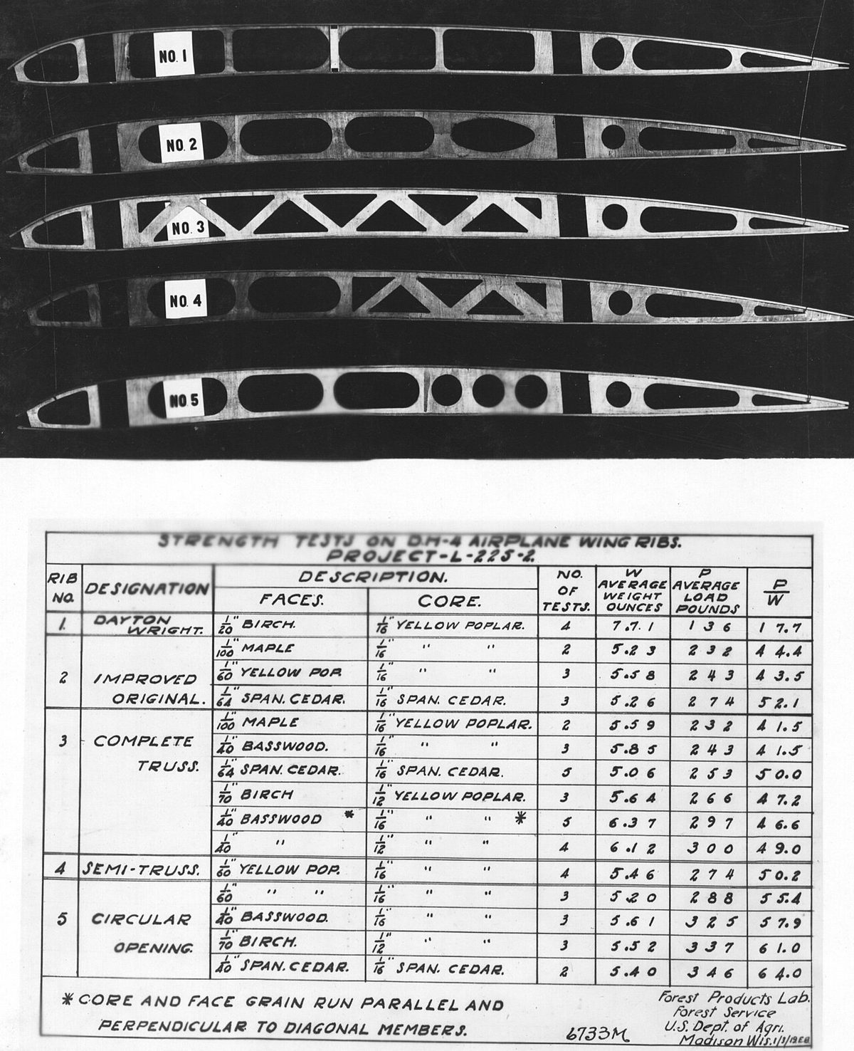
Compliance is shown by analysis supported by tests. Components and complete airframes are loaded in test rigs: a static test article is taken to limit load to show that it does not deform permanently, and on to ultimate load to show that it does not fail. Separate fatigue test articles are cycled through the loads of many simulated flights to find where cracks begin.
Proof and Burst Pressure
Parts that contain pressure, such as wheels, hydraulic components and gas bottles, follow the same logic with pressures in place of loads. The proof pressure is a test pressure above the normal working pressure that the part must withstand without permanent deformation or leakage; it plays the role of the limit load. The burst pressure is a higher pressure that the part must withstand without rupturing, the counterpart of the ultimate load. Both are expressed as multiples of the normal working pressure. For a new wheel design, ATPL texts quote proof pressures of typically 1.5 to 2 times and burst pressures of 3.5 to 4 times the rated tyre inflation pressure, and the wheel must fail, if at all, without throwing out fragments.
The pressure cabin is itself a pressure vessel. It receives an initial proof pressure test before delivery, and its functioning and leak rate are tested again at the intervals set by the maintenance manual, after any actual or suspected malfunction, and after repairs or modifications to the pressure hull (see continuing airworthiness and maintenance).
Primary Structure
Primary structure carries the flight, ground or pressurisation loads and is essential to the structural integrity of the aircraft: the wing spars and the skins and stringers of the wing box, the fuselage frames, skin and pressure bulkheads, the tail surfaces and their attachments, the engine mounts and the landing gear attachments. In a stressed-skin wing the skin is primary structure: it carries spanwise bending and torsion as well as air and fuel pressure loads. Secondary structure, such as fairings and non-structural panels, carries only local loads. Designers can use materials there that they avoid in primary structure, such as magnesium alloys, which are light but corrode easily and burn.
Damage to primary structure is also what makes an occurrence an accident. ICAO Annex 13 counts damage that adversely affects structural strength, performance or flight characteristics and would normally require major repair or replacement, and excludes items such as dented skin, small puncture holes, wing tips and fairings. A bent wing spar qualifies; a dented cowling does not (see accident and incident investigation).
Fatigue and the Design Philosophies
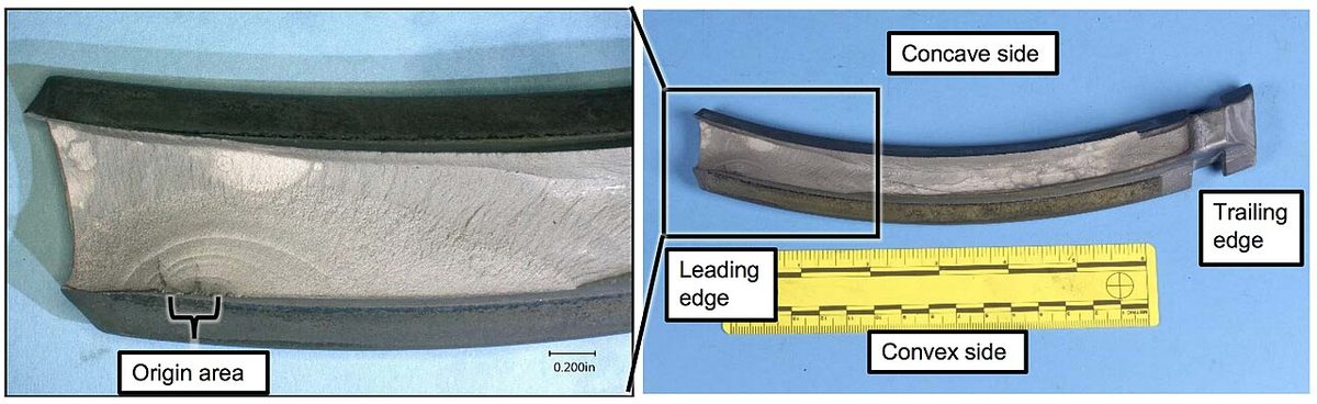
Metal that easily carries a load once can crack when the same load is repeated thousands of times. This is fatigue. A crack starts at a stress concentration, such as a fastener hole, a window or door corner or a cut-out, grows a little with each load cycle, and causes failure when the remaining material can no longer carry the load. Every flight is a load cycle: the fuselage is pressurised and depressurised, the wing is bent up by lift in flight and down by its own weight on the ground, and gusts add smaller cycles on top. Structural life is therefore counted in flight cycles as well as in flight hours.
The de Havilland Comet accidents of 1954, in which fatigue cracks at window corners led to catastrophic failure of the pressure cabin, made fatigue a central design issue. Three philosophies have been used since, often on different parts of the same aircraft (see structural loads, stress and fatigue).
Safe-Life
A safe-life part is designed and tested to survive a predicted number of cycles or hours without failing, with safety margins on the prediction, and is removed from service when it reaches that life, whatever its apparent condition. The approach suits parts that have no alternative load path and in which a crack could not be relied on to be found in time. Typical examples are landing gear components and helicopter rotor parts. Its weakness is that it cannot allow for damage the prediction did not foresee, such as corrosion, a manufacturing flaw or accidental damage.
Fail-Safe
A fail-safe structure has redundant strength: several load paths, so that if one member cracks or fails, the others carry the load until the damage is found at the next scheduled inspection. Fuselage skin panels and wing torsion boxes are designed this way. Passenger cabin windows show the principle in miniature: two acrylic panes in an airtight seal, each able to carry the full pressurisation load on its own. A fail-safe design works only with an inspection programme good enough to find the failed member before a second one fails.
Damage Tolerance
A damage-tolerant structure is designed so that damage, whether from fatigue, corrosion or an accident, grows slowly and predictably and is detected at normal inspections long before it reaches a critical size. It combines the redundancy of fail-safe design with deliberate control of crack growth: loads are spread over large areas so that cracks propagate slowly, and inspection intervals are set by how long a crack of detectable size would take to grow to a critical size. Modern airliners use damage tolerance for their primary structure. The transport-category codes, CS 25.571 and 14 CFR 25.571, require a damage-tolerance evaluation of structure whose failure could be catastrophic, and keep the safe-life approach for structure, such as much of the landing gear, where damage tolerance is shown to be impractical.
| Philosophy | Principle | What keeps it safe | Typical use |
|---|---|---|---|
| Safe-life | Tested to a predicted life | Retirement before failure, whatever its condition | Landing gear parts, helicopter rotor parts |
| Fail-safe | Redundant load paths | Other members carry the load until an inspection finds the damage | Wing torsion boxes, fuselage skin panels, two-pane windows |
| Damage-tolerant | Slow, predictable crack growth | Inspections timed to find cracks before they are critical | Primary structure of modern airliners |
Exam tip: "removed at a fixed life regardless of condition" is safe-life; "multiple load paths" is fail-safe; "damage detected at normal inspection before it becomes critical" is damage-tolerant.
Structural Integrity Programmes
A design philosophy is only as good as the inspections behind it. ICAO Annex 8 requires the State of Design to ensure that a structural integrity programme, including information on corrosion control, exists for aeroplanes with a maximum certificated take-off mass above 5,700 kg. The programme turns the damage-tolerance analysis into structural inspection tasks in each operator's maintenance programme, adds corrosion prevention and control, and is revised as the fleet ages and experience shows where cracks really appear. The State of Registry, for its part, keeps a system for recording faults, malfunctions and defects on the aircraft it registers.
In 1988 a large section of the upper fuselage of Aloha Airlines Flight 243, a Boeing 737, tore away in flight. Fatigue and corrosion had progressed without being caught, and a flight attendant was killed. The accident remains the standard illustration of why inspection programmes must keep pace with an ageing fleet.
Structural integrity also depends on events being reported. Heavy or overweight landings, severe turbulence, overspeeds and load factor exceedances call for the conditional inspections the manufacturer specifies. A heavy landing inspection starts with the landing gear and its attachments, then the structure around the gear bays and the engine mountings. A crew that does not write up the event denies the structure its inspection.
The pilot's own part is to keep the loads inside the design envelope. The flight manual turns the design loads into operating limits: the manoeuvring speed VA, the turbulence penetration speed, VNO or VMO/MMO, the flap and landing gear speeds, the load factor limits and the maximum masses. Fly-by-wire aeroplanes enforce some of these limits themselves; in normal law the A320 limits the load factor to +2.5 g and -1 g clean (see fly-by-wire). Flying beyond them spends a margin that was never meant to be used.
Frequently asked questions
What is the difference between limit load and ultimate load?
The design limit load is the largest load an aircraft is expected to meet in service. The structure must carry it without detrimental permanent deformation, and pilots must never exceed it deliberately. The design ultimate load is the limit load multiplied by a factor of safety of 1.5, and the structure must carry it for at least three seconds without failing. Between the two the structure may be permanently deformed and must be inspected.
Why do aircraft use a factor of safety of 1.5?
The factor of safety covers what cannot be known exactly, such as a gust sharper than the design gust, a harder pull than intended, variations in material strength and workmanship, and the effects of age. Applied to the limit load it gives the ultimate load the structure must survive. It is a margin for the unforeseen, not usable strength, so any exceedance of the limit load is reported and followed by an inspection.
What is the difference between safe-life, fail-safe and damage-tolerant structure?
A safe-life part is tested to a predicted fatigue life and removed from service at that life whatever its condition. A fail-safe structure has redundant load paths, so if one member fails the others carry the load until an inspection finds the damage. A damage-tolerant structure is designed so that cracks grow slowly and are found at normal inspections before they become critical. Modern airliners use damage tolerance for their primary structure.
What is primary structure on an aircraft?
Primary structure carries the flight, ground or pressurisation loads and is essential to the aircraft's structural integrity. Examples are the wing spars and wing box skins, fuselage frames, skin and pressure bulkheads, tail surfaces, engine mounts and landing gear attachments. Secondary structure, such as fairings, carries only local loads. Damage that adversely affects structural strength and would normally need major repair makes an occurrence an accident under ICAO Annex 13.
What are proof pressure and burst pressure?
They are the pressure equivalents of limit and ultimate load. Proof pressure is a test pressure above the normal working pressure that a component, such as a wheel or a hydraulic component, must withstand without permanent deformation or leakage. Burst pressure is a higher pressure it must withstand without rupturing. For a new wheel design, ATPL texts quote proof pressures of about 1.5 to 2 times and burst pressures of 3.5 to 4 times the rated inflation pressure.
Test yourself on Structural Design and Design Loads
The v1prep banks cover this topic in Air Law (010), with a worked explanation for every answer. EASA ATPL, PPL, IR and CPL, the FAA written tests and A320/B737 type ratings.
Start practising →Sources and further reading
- EASA Easy Access Rules for Large Aeroplanes (CS-25), Subpart C, Structure
- 14 CFR Part 25, Subpart C, Structure
- 14 CFR 25.571, Damage-tolerance and fatigue evaluation of structure
- ICAO Annex 8, Airworthiness of Aircraft (ICAO Store)
- FAA Pilot's Handbook of Aeronautical Knowledge (FAA-H-8083-25), Chapter 5, Aerodynamics of Flight
- NTSB AAR-89/03, Aloha Airlines Flight 243, Boeing 737-200, near Maui, Hawaii, 28 April 1988
- NTSB DCA18MA142, Southwest Airlines Flight 1380, left engine failure and depressurization, 17 April 2018
Library articles are written for study and exam preparation. They do not replace your aircraft's approved documentation, your operator's procedures or the regulations themselves.