Structural Loads, Stress and Fatigue
Structural loads are the forces an airframe carries: tension, compression and shear, and their combinations, bending and torsion. They produce stress, force per unit area, and strain, deformation, and when repeated they cause fatigue, cracking at stresses far below those that break the material once.
Every part of an airframe is loaded all the time. On the ground the wings hang from the fuselage and the landing gear carries the weight; in flight the wings bend upwards under lift, the fuselage is inflated by cabin pressure, and gusts and manoeuvres add loads that come and go in seconds. How a structure carries these loads, and how its material responds, decides whether it bends and springs back, deforms permanently, buckles, or cracks after thousands of flights.
This article covers the kinds of load, the measures engineers use to describe a material's response, stress and strain, and the mechanism of fatigue. How the airframe is built to carry the loads is described in airframe structure and construction; the limit and ultimate loads, the factor of safety and the safe-life, fail-safe and damage-tolerant philosophies are in structural design and design loads.
Types of Structural Load
Three basic loads act on a structural member:
- A tensile load (tension) tends to stretch it. Control cables work in tension, as do parts of the structure pulled apart by aerodynamic loads. A member designed to resist tension is a tie.
- A compressive load (compression) tends to shorten it. Undercarriage legs are in compression carrying the aircraft's weight on the ground. A member designed to resist compression is a strut.
- A shear load tends to slide one face of the material over the adjacent face. Rivets, bolts and skin panels are the classic shear carriers; rivets transfer load between skin panels in shear and have little strength in tension.
Two further loads are combinations of these. Bending puts the outer, convex edge of a member in tension, the inner, concave edge in compression, and the material across it in shear. A wing bending upwards in flight has its upper skin in compression, its lower skin in tension and its internal structure in shear; on the ground, hanging under its own weight, the loads reverse. Torsion is twisting about the member's axis. It sets up shear stress in the material, greatest at the outer surface and zero on the axis, which is why a closed tube or box resists it far better than an open section of the same weight. The wing meets torsion from aerodynamic pitching moments and from deflected ailerons, and carries it as shear in the skins and spar webs of its closed torsion box.
| Load | Effect | Aircraft example | Resisted by |
|---|---|---|---|
| Tension | Stretches | Control cables | Ties |
| Compression | Shortens | Landing gear legs on the ground | Struts |
| Shear | Slides one face over the next | Riveted skin joints | Rivets, skin panels |
| Bending | Tension, compression and shear together | Wing in flight | Spars, stiffened skins |
| Torsion | Twists, producing shear | Wing, fin | Closed torsion box |
Stress and Strain
A load on a member produces stress, the internal force per unit area of the material: stress = force ÷ area. It is expressed in N/mm² or MN/m², which are the same quantity (both equal to 1 MPa). Tension produces tensile stress, compression compressive stress. Stress is what a material "feels", so the same load is more severe in a thinner part.
The material responds by deforming. Strain is that deformation, expressed as the change in a dimension divided by the original dimension, as a fraction or a percentage. Because it is a ratio of two lengths, strain has no units. A tensile stress produces a tensile strain, an elongation.
The distinction matters in maintenance as much as in design. Strength ratings, such as yield stress or ultimate stress, are stated in stress units; damage is often detected as strain, a wing or a skin panel that has taken a permanent set.
Elastic and Plastic Deformation
If a metal specimen is loaded gradually in tension, its strain at first rises in step with the stress. Remove the load and the specimen returns to its original dimensions: this is elastic deformation. The highest stress at which this remains true is the elastic limit.
Beyond the elastic limit, part of the deformation remains when the load is removed. This is plastic deformation: the part is permanently stretched, bent or dented. Loaded further still, the material reaches its ultimate tensile strength (UTS), the greatest stress it can carry in tension, and then fails.
Aircraft structure must work within the elastic limit. Permanent deformation is evidence of serious overstress, which is why the design limit load is defined as the load the structure must carry without detrimental permanent deformation, and why an overstressed aircraft is inspected for buckled skins, pulled rivets and bent members before it flies again.
Hooke's Law and Young's Modulus
Within the elastic limit, stress is proportional to strain. This is Hooke's law. The constant of proportionality is Young's modulus of elasticity, E:
E = stress ÷ strain
Young's modulus measures stiffness, how much a material deforms under a given stress, not strength, how much stress it can carry before it yields or breaks. A stiff material has a high modulus and stretches little. Stiffness matters to the airframe in its own right: a wing that twists too easily loses aileron effectiveness at high speed and is more prone to flutter, even if it is strong enough.
Hoop and Axial Cabin Stresses
A pressurised fuselage is a pressure vessel. The cabin differential pressure, which ATPL texts quote at up to 65.5 kN/m² (9.5 psi), loads the skin in two directions:
- Hoop stress acts around the circumference and tries to expand the cross-section.
- Axial stress (longitudinal stress) acts along the length and tries to make the fuselage longer.
For a thin-walled cylinder of radius r and skin thickness t under a pressure differential P, the hoop stress is P × r ÷ t and the axial stress P × r ÷ 2t. The hoop stress is therefore twice the axial stress, and a larger fuselage diameter needs a thicker skin for the same differential. Both stresses are applied once and removed once on every flight, so the pressure hull accumulates one major fatigue cycle per flight however long the flight is (see pressurisation principles and control).
Buckling and Stress Concentration
Buckling is the failure of a thin or slender member under compression: it bows sideways and collapses at a load far below what the material could carry in direct compression. Thin skin panels buckle under end loads, and slender members designed as ties buckle if the load reverses and puts them in compression. Stringers and stiffeners prevent it by dividing the skin into shorter panels, each far more resistant to buckling than a large unsupported sheet. A wrinkled skin panel after a heavy landing or a severe turbulence encounter is a sign that buckling has occurred.
A stress concentration is a local rise in stress wherever the smooth flow of load through a part is interrupted: a rivet or fastener hole, a sharp corner at a cut-out, a scratch, a crack or a contaminant in the material. Windows, doors and access panels are unavoidable stress raisers in a fuselage. Designers reduce the peak with smooth radii at corners, polished surfaces and doublers around openings, and by cold-working fastener holes to leave a residual compressive stress around them that delays cracking.
Static and Dynamic Loads
Static loads are generally constant and build slowly, like the weight of a parked aeroplane on its landing gear and wing structure. Dynamic loads build quickly as flight conditions change, in manoeuvres, gusts, turbulence and landings. They are often more severe than static loads and can induce additional loads elsewhere in the structure. A wing spar sees both kinds: bent downwards by weight on the ground and upwards by lift in flight, with the gusts of every flight superimposed.
The size of the flight loads is measured by the load factor, and the structure is designed for limit load factors set by the certification codes (see load factor and flight envelope). The pilot's control over dynamic loads is speed and handling: slowing to the turbulence penetration speed, avoiding abrupt control inputs at high speed, and making a firm but not heavy landing.
Structural Fatigue
Structural fatigue is progressive failure under cyclic, repeated loading at stresses far below those that would break the material in a single application. A fatigue crack begins at a stress concentration, grows a little with each load cycle, and causes sudden failure when the remaining material can no longer carry the load. Fatigue cracks almost always start at stress concentrations: rivet holes, sharp corners at cut-outs and brackets, surface defects such as scratches and manufacturing flaws, and contaminants in the material.
The number of cycles a metal survives depends very strongly on the stress. ATPL texts illustrate it with a part loaded to 80 per cent of its ultimate stress failing after about 100 cycles, and one loaded to 20 per cent surviving 10 million cycles or more. The relationship is so non-linear that a modest reduction in working stress greatly extends fatigue life, one reason for the margins built into airframes and one reason load limits matter even when an exceedance breaks nothing.
An airliner experiences millions of load cycles in its life, one large pressurisation and wing-bending cycle per flight and many smaller ones from gusts, so structural life is counted in flight cycles as well as flight hours.
Composites behave differently from metals. ATPL texts note that fatigue is not generally a concern in composites at stresses below about 80 per cent of their ultimate stress and that they lose their properties gradually, whereas a metal keeps its design strength up to a critical point and then fails rapidly as the crack runs. Undetected fatigue in metal is therefore the more dangerous, which is why metal primary structure is inspected on a schedule designed to find cracks while they are still small.
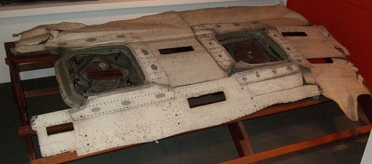
Both of the accidents that every structures course recalls, the de Havilland Comet losses of 1954 and Aloha Airlines Flight 243 in 1988, began at stress concentrations in a pressure hull cycled on every flight; they, and the safe-life, fail-safe and damage-tolerant philosophies that followed, are described in structural design and design loads.
Exam tip: stress is force per unit area (N/mm²); strain is deformation over original size (no units); Young's modulus is stress divided by strain, constant within the elastic limit (Hooke's law). Elastic deformation springs back, plastic deformation is permanent. Hoop stress is twice axial stress. Torsion is carried as shear. Fatigue cracks start at stress concentrations.
Frequently asked questions
What are the five types of load on an aircraft structure?
The three basic loads are tension, which stretches a member, compression, which shortens it, and shear, which slides one part of the material over the next. Bending and torsion are combinations of them. A bent member is in tension on its outer edge, in compression on its inner edge and in shear across it; a twisted member is mainly in shear. Members built to resist tension are called ties, and those built to resist compression are called struts.
What is the difference between stress and strain?
Stress is the internal force per unit area inside a part that results from an external load, measured in N/mm² or MN/m². Strain is the deformation that the stress produces, the change in a dimension divided by the original dimension, so it has no units. Within the elastic limit the two are proportional, which is Hooke's law, and the ratio of stress to strain is Young's modulus of elasticity.
What is hoop stress in a pressurised fuselage?
Hoop stress is the stress that cabin pressure produces around the circumference of the fuselage, trying to expand its cross-section. Pressure also produces axial stress along the length, trying to make the fuselage longer. For a thin cylinder the hoop stress is twice the axial stress, which is why fuselage skins are designed first for hoop stress. Each flight applies and removes these stresses once, a pressurisation cycle that counts towards fatigue.
Why do fatigue cracks start at rivet holes and window corners?
A hole, a sharp corner, a scratch or a flaw interrupts the smooth flow of load through a part, and the stress rises locally around it. This is a stress concentration, and fatigue cracks almost always start at one. Designers reduce the peak with generous corner radii, polished surfaces, doublers around openings and cold-worked fastener holes, and maintenance programmes look for cracks at these points first.
How does the stress level affect fatigue life?
The relationship is strongly non-linear. ATPL texts quote a metal part loaded to 80 per cent of its ultimate tensile strength failing after about 100 cycles, while at 20 per cent it may survive 10 million cycles or more. A small reduction in the working stress therefore gives a large increase in fatigue life, which is why structures are designed with generous margins and why exceeding load limits shortens a structure's life even when nothing breaks.
Test yourself on Structural Loads, Stress and Fatigue
The v1prep banks cover this topic in Aircraft General Knowledge (021), with a worked explanation for every answer. EASA ATPL, PPL, IR and CPL, the FAA written tests and A320/B737 type ratings.
Start practising →Sources and further reading
- FAA Aviation Maintenance Technician Handbook, Airframe (FAA-H-8083-31B), Chapter 1, Aircraft Structures
- FAA Pilot's Handbook of Aeronautical Knowledge (FAA-H-8083-25), Chapter 3, Aircraft Structure
- EASA Easy Access Rules for Large Aeroplanes (CS-25), Subpart C, Structure
- 14 CFR 25.571, Damage-tolerance and fatigue evaluation of structure
- NTSB AAR-89/03, Aloha Airlines Flight 243, Boeing 737-200, near Maui, Hawaii, 28 April 1988
Library articles are written for study and exam preparation. They do not replace your aircraft's approved documentation, your operator's procedures or the regulations themselves.