Airframe Structure and Construction
The airframe is the structure of an aircraft: fuselage, wings, empennage, landing gear and engine mountings. Modern aircraft use semi-monocoque stressed-skin construction, in which a load-carrying skin is stiffened by frames and stringers and the wing is built around a spar and skin torsion box.
The airframe is the aircraft without its engines and systems: the fuselage, the wings, the empennage or tail unit, the landing gear and the structure that carries the engines. Each part is a set of members shaped to carry particular loads, joined so that the loads flow from where they arise, such as the lift on the wing or the weight of a passenger, to where they are balanced.
How an airframe is built explains much of what pilots are taught to respect: why a small skin dent near a window matters, why a tail strike is followed by an inspection of the rear pressure bulkhead, and why fuel in the outer wing is used last. The loads themselves, and how materials respond to them, are covered in structural loads, stress and fatigue; the loads the structure is designed for are in structural design and design loads.
- Main Components of the Airframe
- Truss and Monocoque Construction
- Semi-Monocoque Stressed-Skin Structure
- Fuselage Frames, Stringers and Longerons
- Wing Spars, Ribs and Torsion Box
- Pressure Hull and Pressure Bulkheads
- Empennage, Tail Cone and Radome
- Doublers, Repairs and Fuselage Stretches
- Frequently asked questions
Main Components of the Airframe
The fuselage is the main body of the aircraft. It carries the payload, houses the flight crew with their controls and instruments and the cabin crew with their equipment, and transfers loads between the wings, the tailplane and fin, the landing gear and, on some types, the engines. Structurally it behaves as a long beam, supported in flight by the wings and on the ground by the landing gear.
The wings carry the lift, the fuel on most aeroplanes and, on many, the engines and main landing gear. The empennage, described below, provides stability and control in pitch and yaw.
Every point on the structure has an address. Station numbers give fore-and-aft positions, measured in inches from a zero datum at or near the front of the fuselage, water lines give vertical positions from a horizontal datum, and wing stations give distances from the aircraft centreline. Maintenance manuals, repair drawings and damage reports use these references.
Truss and Monocoque Construction
The earliest aircraft, and many light aircraft since, use a truss structure: a framework of wood or, later, welded steel tubes, braced into triangles and covered with fabric. The covering carries no load. Each member is loaded mainly in tension or compression: a member built to resist tension is a tie, one built to resist compression is a strut.
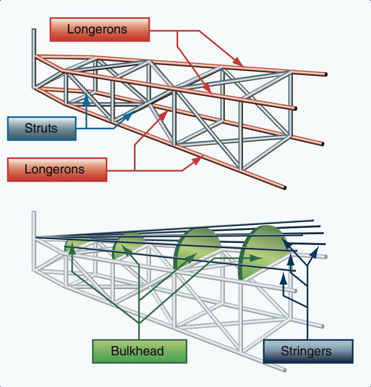
A truss is simple and easily repaired, but it is heavy for its strength and fills the fuselage with bracing. Monocoque construction, literally single-shell construction, does the opposite: the skin carries all the loads, and internal formers or frames only give the cross-section its shape. There are no longerons or stringers. The shell is efficient in small sizes, but even slight skin damage seriously weakens a monocoque structure, and every hole for a window, door or undercarriage bay needs local reinforcement. For a large fuselage the skin alone would have to be too thick and too heavy, so pure monocoque is limited to small aircraft.
Semi-Monocoque Stressed-Skin Structure
Semi-monocoque construction is the standard for transport aircraft and for most modern light aeroplanes. A light alloy or composite skin is attached, by riveting or adhesive bonding, to frames that run around the fuselage and to stringers and longerons that run fore and aft between them. The load is shared: the internal members carry part of it and stiffen the skin, and the skin carries the rest. Because the skin is a working part of the structure, this is also called stressed-skin construction.
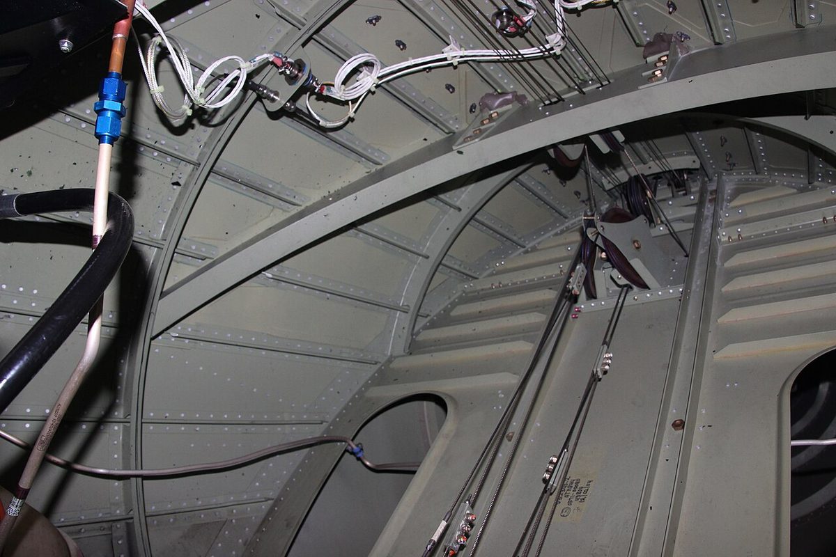
A semi-monocoque structure is stronger for its weight than a pure shell, and it tolerates damage better, because the loads have several paths. It is the reason a transport aircraft's skin is primary structure and why unreported damage to it is taken seriously.
Fuselage Frames, Stringers and Longerons
The members of a semi-monocoque fuselage each have a distinct job:
| Member | Direction | Function |
|---|---|---|
| Frame (former) | Around the fuselage | A hoop open in the centre; keeps the shape and passes major loads from skin and stringers to the rest of the structure |
| Bulkhead | Across the fuselage | Like a frame but essentially solid; the front and rear pressure bulkheads close the pressure hull |
| Stringer | Fore and aft, closely spaced | Stiffens the skin against buckling and helps it carry longitudinal loads |
| Longeron | Fore and aft, fewer and heavier | Carries the main bending loads of the fuselage; often below the floor |
| Crossbeam (floor beam) | Side to side | Strengthens the structure and supports the passenger or cargo floor |
Stringers break the compressive load path in the skin into shorter panels, which resist buckling far better than a large unsupported sheet. Longerons are larger in section and fewer in number; ATPL texts give the passenger seat rails as an example. Crossbeams carry the floor panels, often of sandwich or honeycomb material, and pass the loads of passengers, seats and cargo into the frames.
A firewall is a special bulkhead that separates an engine from the flight deck and cabin. It is made of heat-resistant stainless steel or titanium alloy, and ATPL texts quote the requirement that it withstand a flame of about 1,100 °C (2,000 °F) for at least 15 minutes.
Wing Spars, Ribs and Torsion Box
Almost every modern aeroplane is a cantilever monoplane: a single wing on each side with no external struts or bracing wires, so that all bending and twisting loads are carried inside the wing. Braced monoplanes, with a strut from the fuselage to the wing, remain common among light high-wing aeroplanes, and early biplanes were braced with wires and struts.
The spar, or wing spar, is the main spanwise beam. It carries the bending loads: upwards in flight, when lift acts along the span, and downwards on the ground, when the wing hangs from the fuselage under its own weight and that of its fuel and engines. The bending moment is greatest at the wing root, so the structure is heaviest there and tapers towards the tip.
Ribs run chordwise, from leading edge to trailing edge. They keep the aerofoil shape, support the spars, stringers and skin against buckling, and feed concentrated loads, from engine pylons, landing gear attachments, control surface hinges and fuel, into the skin and spars.
On a transport aircraft the front spar, the rear spar and the upper and lower skins form a closed box, the torsion box. The closed section resists twisting through shear in the skins and carries bending, with the upper skin in compression and the lower skin in tension in flight. Stringers stiffen the skins, and the box is sealed to form integral fuel tanks. The part of the box that runs through the fuselage and joins the two wings is the centre section, or centre wing box, and it too may be sealed as a tank; on the Boeing 737, for example, the centre fuel tank lies between the wing roots within the fuselage and extends into the wing.
The mass in the wing works in the structure's favour. Fuel and engines hung under the wing push down against the upward bending of lift and reduce the root bending moment, and the further outboard the mass, the greater the relief. That is why fuel in the outer wing is used last (see maximum structural and regulated masses). Engines on pylons ahead of the wing also act as mass balances against flutter.
Pressure Hull and Pressure Bulkheads
A pressurised aircraft carries a pressure hull: the part of the fuselage, from the front pressure bulkhead to the rear pressure bulkhead, that holds the cabin, the flight deck and most cargo compartments at a higher pressure than outside. The nose radome, the undercarriage bays, the tail cone, the wing interior and the engine pylons are unpressurised.
Pressurisation stretches the hull around its circumference (hoop stress) and along its length (axial stress), and every flight is one pressurisation cycle, which is why the pressure hull is a fatigue-critical structure. The stresses themselves are explained in structural loads, stress and fatigue.
Openings in the hull are designed so that pressure helps rather than hinders. Passenger doors are plug-type doors, larger than their frames, so that cabin pressure pushes them against the frame, and they cannot be opened in flight while the cabin is pressurised. Cabin windows have two acrylic panes, each able to carry the full pressure load alone (see structural design and design loads). Flight deck windows are panes of toughened glass bonded to a clear vinyl interlayer that stretches to absorb a bird strike, and CS-25 requires the windscreen to withstand a 4 lb (1.8 kg) bird at the design cruising speed VC at sea level, or 0.85 VC at 8,000 ft, whichever is more critical (see pressurisation principles and control).
Empennage, Tail Cone and Radome
The empennage (tail unit) provides longitudinal and directional stability and control. The horizontal stabiliser or tailplane produces upward or downward force as required, with the elevators for pitch control; the vertical stabiliser or fin produces side force, with the rudder for yaw control. The fin is loaded in both bending and torsion in flight. Tailplane and fin are built like small wings, with spars, ribs and skins; the layouts, conventional, T, cruciform, H and V, are compared in tail configurations.
The tail cone closes the rear of the fuselage behind the rear pressure bulkhead. It is unpressurised and, on airliners such as the A320 and the Boeing 737, houses the auxiliary power unit. At the other end, the radome is the nose cone that covers the weather radar antenna. It is made of a material transparent to the radar's microwave energy while protecting the antenna; water or ice on it absorbs energy and weakens the returns.
Doublers, Repairs and Fuselage Stretches
Any cut-out in a stressed skin interrupts the load path and concentrates stress around its edge. A doubler, or backing plate, is a reinforcement fitted around windows, doors, access panels and repairs to compensate. Where the skin is machined from solid, the metal around an opening is left thicker instead. Without such reinforcement a cut-out would crack quickly in service.
Repairs follow the same logic: a damaged area is cut out and replaced or reinforced so that the load path and its fatigue life are restored, using the manufacturer's structural repair data. Poor repairs have caused accidents long after the damage itself. Japan Air Lines Flight 123, a Boeing 747 lost in 1985 with 520 dead, suffered the failure of a rear pressure bulkhead that had been repaired incorrectly after a tail strike seven years earlier, and China Airlines Flight 611, a 747 that broke up in flight in 2002, failed along fatigue cracks hidden by an inadequate repair of tail strike damage to the rear fuselage skin made in 1980. A tail strike is therefore written up and inspected, with particular attention to the aft fuselage and the rear pressure bulkhead, and a nosewheel-first landing calls for an inspection of the front pressure bulkhead.
Semi-monocoque construction also makes it possible to lengthen an existing design. A fuselage plug, or stretch, is a constant-section barrel inserted into the fuselage. The Airbus A321 is the A320 with plugs added ahead of and behind the wing; the forward plug alone increases the wheelbase, from 12.64 m to 16.91 m, and the aircraft is 44.51 m long.
The A320 is a narrow-body aircraft: a single-aisle fuselage with an internal cabin width of 3.70 m at armrest level and six seats abreast, three on each side. The cross-section is fixed when the type is designed; later versions change the length. A wide-body aircraft has a fuselage wide enough for two aisles.
Exam tip: frames and bulkheads run around the fuselage, stringers and longerons along it. Stringers stiffen the skin; longerons take the main bending loads; frames keep the shape; bulkheads are solid and close the pressure hull. In the wing, spars take bending, ribs keep the shape, and spars plus skins form the torsion box.
Frequently asked questions
What is the difference between monocoque and semi-monocoque construction?
In a monocoque structure the skin carries all the loads and the internal formers only give the cross-section its shape, so a small area of skin damage seriously weakens it and it suits only small aircraft. A semi-monocoque structure adds stringers and longerons running fore and aft to the frames, so the skin is stiffened and the load is shared between skin and internal members. Almost every modern aircraft uses it.
What is the function of a wing spar?
The spar is the main spanwise beam of the wing. It carries the bending loads, upwards in flight when lift acts on the wing and downwards on the ground under the wing's own weight. Most transport aircraft have a front and a rear spar, which together with the upper and lower skins form a closed torsion box that also resists twisting. The bending moment, and so the size of the spar, is greatest at the wing root.
What is the difference between a frame and a bulkhead?
A frame, or former, is a hoop around the fuselage cross-section that is open in the centre, so the cabin space can be used. It keeps the fuselage in shape and passes loads from the skin and stringers to the rest of the structure. A bulkhead is similar but essentially solid. The front and rear pressure bulkheads close the ends of the pressure hull, separating the pressurised cabin from the unpressurised nose and tail.
What is a torsion box in an aircraft wing?
A torsion box is the closed structural box formed by the front spar, the rear spar and the upper and lower wing skins. Because it is closed, it resists twisting through shear in the skins, and it also carries bending, with the upper skin in compression and the lower skin in tension in flight. Stringers stiffen the skins against buckling, ribs keep the shape, and on airliners the box also forms the integral fuel tanks.
What is a doubler in aircraft structure?
A doubler is a reinforcing plate fitted around a cut-out or a repair in a stressed skin, for example around windows, doors and access panels. Any hole interrupts the load path and concentrates stress at its edges, which is where fatigue cracks start. The doubler spreads the load back out. In skins machined from solid, the metal around the opening is simply left thicker to do the same job.
Test yourself on Airframe Structure and Construction
The v1prep banks cover this topic in Aircraft General Knowledge (021), with a worked explanation for every answer. EASA ATPL, PPL, IR and CPL, the FAA written tests and A320/B737 type ratings.
Start practising →Sources and further reading
- FAA Pilot's Handbook of Aeronautical Knowledge (FAA-H-8083-25), Chapter 3, Aircraft Structure
- FAA Aviation Maintenance Technician Handbook, Airframe (FAA-H-8083-31B), Chapter 1, Aircraft Structures
- EASA Easy Access Rules for Large Aeroplanes (CS-25), Subpart C, Structure
- 14 CFR Part 25, Subpart C, Structure
- ICAO Annex 8, Airworthiness of Aircraft (ICAO Store)
Library articles are written for study and exam preparation. They do not replace your aircraft's approved documentation, your operator's procedures or the regulations themselves.