A320 Landing Gear, Brakes and Steering
The A320 landing gear system comprises the retractable tricycle gear and its two control and interface units, the nosewheel steering, and carbon brakes on the four main wheels, controlled by a brake and steering control unit with anti-skid and autobrake and backed by an alternate braking system.
The A320 has a conventional tricycle landing gear, but almost everything about it is managed by computers. Two control and interface units sequence the gear and tell the rest of the aircraft whether it is in the air or on the ground. A brake and steering control unit turns pedal, tiller and autopilot inputs into brake pressure and nosewheel angle, with anti-skid and autobrake. Behind it stand an alternate braking system, an accumulator, the parking brake and a crank that lowers the gear by gravity.
The design gives several layers of protection, and the crew must know which layer they are in. The braking mode depends on the hydraulic systems available and the position of one switch, and the loss of braking memory items work through those layers in order. The general principles are covered in landing gear retraction and extension, anti-skid and autobrake and nose wheel steering.
Landing gear overview
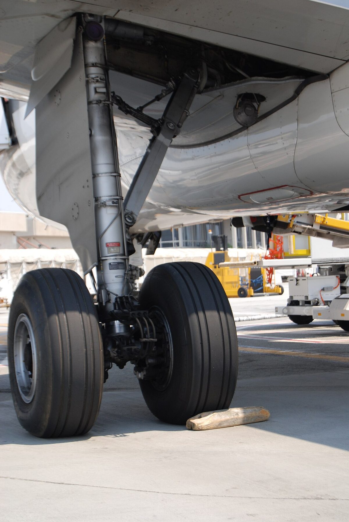
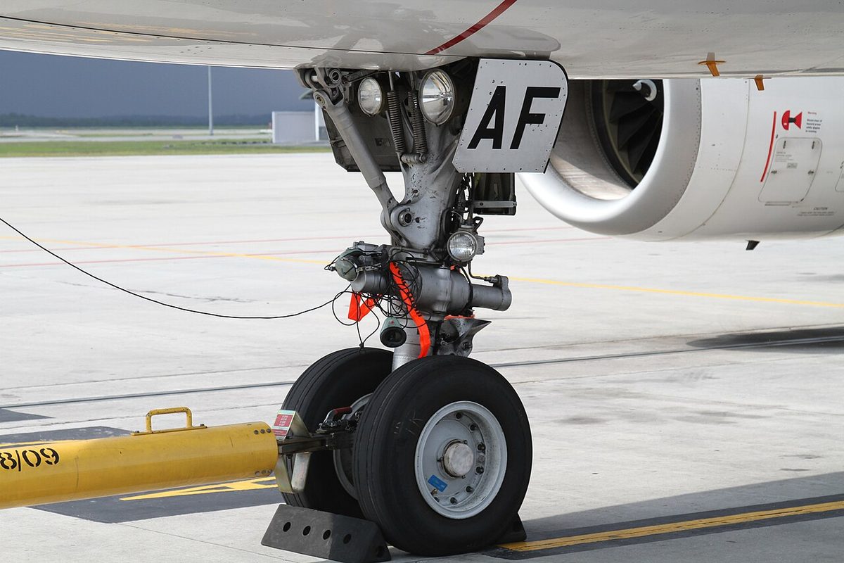
The A320 has two main landing gears that retract inboard and a nose landing gear that retracts forward. Each main gear has twin wheels and an oleo-pneumatic shock absorber, and each main wheel has a carbon multidisc brake with anti-skid. The two-wheeled nose gear has an oleo-pneumatic shock strut and the nosewheel steering. Gear and doors are electrically controlled and hydraulically operated, all by the green hydraulic system (see A320 hydraulic system). The doors on the gear legs are moved mechanically by the gear; the other doors open while the gear is moving and close at the end of the cycle.
The crew use a two-position lever on the centre instrument panel, always moved in one continuous movement. An interlock locks it DOWN when either main gear shock absorber is compressed or the nosewheel steering is not centred. When UP is selected, the normal brakes stop the main wheels while the doors open, and on aircraft with nose gear rubbing strips a brake band in the nose gear well stops the nosewheels as the doors close.
| Limit | A320 |
|---|---|
| VLO, extension | 250 kt / M 0.60 |
| VLO, retraction | 220 kt / M 0.54 |
| VLE | 280 kt / M 0.67 |
| Tyre speed | 195 kt ground speed (195.5 kt in the EASA type certificate data sheet) |
LGCIU and gear indications
Two landing gear control and interface units (LGCIUs) control gear extension and retraction and the doors, supply landing gear information to the ECAM and send air/ground signals to many other systems. Their proximity detectors report the gear locked up or down, shock absorber compression and the door positions. One LGCIU controls a complete gear cycle and hands over to the other at the end of each retraction, or if it fails; the remaining unit then controls the gear alone.
The gear position is shown in two places:
- The LDG GEAR indicator panel is connected to LGCIU 1 only. A green ▽ light shows a gear locked down; a red UNLK light shows a gear not locked in the selected position.
- The WHEEL system display page shows two triangles for each gear, one from each LGCIU. Green means downlocked, red in transit, no triangle uplocked, and amber crosses replace a triangle if its LGCIU has failed. One green triangle on each gear is enough to confirm it is down, and the LDG GEAR DN line of the landing memo confirms it too.
A red arrow on the gear lever lights, with a red ECAM warning, if the gear is not locked down when the aircraft is in the landing configuration. The amber L/G CTL legend and caution mean that lever and gear disagree, but it does not appear while the gear is moving normally.
Normal and gravity extension
The lever signals the LGCIUs, which control the green hydraulic supply through selector valves. All doors open, each gear moves to the selected position, and the doors close. A landing gear safety valve cuts off the hydraulic supply to the landing gear system above 260 kt; below 260 kt the supply stays cut off as long as the lever is up. With the gear down, the system stays pressurised as long as green pressure is available.
If hydraulic or electrical power is lost, the crew use gravity extension. They pull out the hand crank on the centre pedestal and turn it clockwise for three turns. This isolates the gear hydraulics from the green system, unlocks the doors and the gears, and lets gravity drop them. Locking springs help the main gears into the downlocked position and aerodynamic forces help the nose gear. The doors remain open. After a training use in flight, the system can be reset if green pressure is available.

Nosewheel steering
A hydraulic cylinder supplied by the yellow system steers the nosewheels, on electrical signals from the brake and steering control unit (BSCU). The BSCU takes orders from the two steering hand wheels, which are interconnected and add their inputs algebraically, from the rudder pedals and from the autopilot, and turns them into a steering angle whose limits depend on the ground speed and the source of the order.
| Source | Nosewheel angle |
|---|---|
| Hand wheels (tillers) | up to 75° either way |
| Rudder pedals at low speed | ± 6° at full pedal deflection |
| Towing, steering deactivated | up to 95° either way |
Steering authority decreases as ground speed increases, and the link between rudder pedals and nosewheel steering is removed at 130 kt wheel speed; in a strong crosswind take-off, more rudder is then needed. The steering receives hydraulic pressure only when the A/SKID & N/W STRG switch is ON, the towing lever is in its normal position, at least one engine is running and the aircraft is on the ground. After take-off the nosewheel is centred by an internal cam.
The PEDALS DISC pushbutton on either hand wheel removes rudder pedal and autopilot orders from the steering while it is held. The crew use it during the flight control check, when the pilot flying applies full rudder without turning the nosewheel. If steering is lost, N/W STEERING appears in amber on the WHEEL page.
Normal braking and anti-skid
The main wheel brakes can be applied by two independent systems. Normal braking uses green hydraulic pressure and is controlled by the dual-channel BSCU, which changes channel at each DOWN selection of the gear lever or when a channel fails. It is available when green pressure is available and the A/SKID & N/W STRG switch is ON, and it brings anti-skid and autobrake. The BSCU commands it from the pedals, from the autobrake, or automatically during gear retraction. It also checks residual brake pressure, monitors brake temperatures and sends wheel speeds to other systems. There is no brake pressure indication in the cockpit during normal braking.
Anti-skid holds each wheel at the limit of an impending skid, where braking is most efficient. When a wheel's speed falls below about 0.87 times the anti-skid reference speed, the BSCU orders brake release. The reference speed comes from the horizontal acceleration measured by ADIRU 1, 2 or 3; if all the ADIRUs have failed, it is the higher of the two main gear wheel speeds. Anti-skid is deactivated below 20 kt ground speed, so the aircraft can be brought to a stop. Without autobrake, full braking needs full pedal deflection.
Alternate braking and the ABCU
The alternate braking system uses the yellow hydraulic system, backed up by a brake accumulator. Its modes are:
- Alternate braking with anti-skid, used when green pressure is insufficient, yellow is available, the A/SKID & N/W STRG switch is ON and the parking brake is not on. Pedal inputs go to the alternate braking control unit (ABCU), which pressurises the yellow brake circuit and controls the alternate servo valve, while the BSCU still provides anti-skid. Autobrake is lost, and the first part of pedal travel gives more braking than in normal mode.
- Alternate braking without anti-skid, entirely under ABCU control. Anti-skid is lost electrically when the switch is OFF, when its power supply fails or when the BSCU fails. Brake pressure is then limited automatically to 1,000 psi, to avoid locking the wheels and limit the risk of a tyre burst.
- Accumulator only, without anti-skid, when both yellow and green pressure are low. The accumulator gives at least seven full brake applications.
The triple brake indicator, labelled BRAKES and ACCU PRESS, shows the yellow pressure delivered to the left and right brakes, measured upstream of the alternate servo valves, and the accumulator pressure. It therefore normally shows brake pressure only in alternate braking or with the parking brake set. The parking brake is supplied by the yellow system or the accumulator, which holds parking pressure for at least 12 hours; engine 2 is usually started first because it pressurises the yellow system.
Autobrake modes
The autobrake is armed with the spring-loaded LO, MED and MAX pushbuttons, provided green pressure is available, anti-skid is powered, the braking system has no failure and at least one ADIRU is available. MAX cannot be armed in flight. A blue ON light confirms arming, and a green DECEL light comes on when the actual deceleration reaches 80 % of the selected rate.
| Mode | Use | Braking starts | Target |
|---|---|---|---|
| LO | Landing | 4 s after ground spoiler extension | 1.7 m/s² (5.6 ft/s²) |
| MED | Landing | 2 s after ground spoiler extension | 3 m/s² (9.8 ft/s²) |
| MAX | Take-off | At the ground spoiler extension order | Maximum pressure |
Braking is triggered by the ground spoiler extension command, and at least two SECs must be working; in MAX the wheel speed must also be above 72 kt. If the ground spoilers do not extend, the autobrake does not act, so after a rejected take-off below 72 kt or a landing without spoilers the pilots brake with the pedals. The autobrake deactivates but stays armed if the ground spoilers retract, and it disarms when the crew press the pushbutton, an arming condition is lost, after take-off or a touch-and-go, or when a pilot applies enough pedal deflection. On landing, the pilot flying disengages it with the pedals before 20 kt.
Exam tip: on a slippery runway the DECEL light may not come on because the anti-skid limits the deceleration. That does not mean the autobrake has failed.
Brake temperature and brake fans
The WHEEL page shows each brake temperature in green. A green arc appears over the hottest wheel above 100 °C and turns amber, with an ECAM caution, above 300 °C. The maximum brake temperature for take-off is 300 °C with the brake fans off. Fusible plugs in the main wheels protect against tyre burst when the wheels overheat.
The optional brake fans run when their pushbutton is ON and the left main gear is down and locked; an amber HOT light comes on when the brakes are too hot. With the fans running, the indicated temperature is lower than the actual one, by 50 °C at an actual 100 °C up to 150 °C at an actual 300 °C. With the fans running, the take-off is delayed if any indicated temperature is above 150 °C. The fans are not used for take-off, to avoid foreign object damage. After landing they are switched on without delay for a short turnaround or if a brake is likely to exceed 500 °C, otherwise 5 minutes after landing or when approaching the gate, whichever comes first. The parking brake should not be applied when a brake is above 500 °C (350 °C with fans), unless operationally necessary.
Carbon brake wear depends on the number of brake applications and on brake temperature, not on the pressure applied or the duration of braking, and repeated high temperatures, above 400 °C in particular, oxidise the discs. Airbus therefore recommends autobrake LO when performance allows. See brake energy and tyre speed limits.
Loss of braking
If there is no braking after touchdown, the crew apply the loss of braking memory items:
- REV: MAX. Maximum reverse may be kept until the aircraft stops.
- BRAKE PEDALS: RELEASE.
- A/SKID: OFF. The pilot flying orders it and the pilot monitoring sets the A/SKID & N/W STRG switch OFF.
- BRAKE PEDALS: PRESS.
- MAX BRK PR: 1,000 psi, monitored on the triple indicator.
- If there is still no braking: PARK BRAKE, in short successive applications.
Switching the A/SKID & N/W STRG switch OFF transfers braking from the BSCU to the ABCU and activates alternate braking, which is why the pedals are released first: otherwise the change could give a sudden, violent brake application.
Warning: with the switch OFF there is no anti-skid and no nosewheel steering. Directional control comes from the rudder and differential braking, with the brake pressure limited to 1,000 psi.
Frequently asked questions
What does the A/SKID and N/W STRG switch do on the A320?
With the switch ON, the brake and steering control unit provides normal braking with anti-skid on the green system and nosewheel steering. Selecting it OFF transfers braking to the alternate system on the yellow hydraulics without anti-skid, with the brake pressure limited to 1,000 psi, and removes nosewheel steering. Differential braking with the pedals remains available. It is the key action of the loss of braking memory items.
What are the A320 loss of braking memory items?
If there is no braking after touchdown: reverse thrust maximum; brake pedals released; the pilot flying orders A/SKID OFF and the pilot monitoring sets the A/SKID and N/W STRG switch OFF; brake pedals pressed, with the brake pressure, limited to 1,000 psi, monitored on the triple indicator. If there is still no braking, the parking brake is used in short successive applications. The pedals are released first because switching to alternate braking could otherwise cause a sudden, violent brake application.
What does the DECEL light mean on the A320 autobrake?
The green DECEL light on the autobrake pushbutton comes on when the actual deceleration reaches 80 per cent of the selected rate. On a slippery runway the anti-skid may stop the aircraft reaching that rate, so the light may stay off even though the autobrake is working. It shows deceleration achieved, not that the autobrake is engaged.
How is the A320 landing gear extended by gravity?
The crew pull out the gravity extension crank on the centre pedestal and turn it clockwise for three turns. This isolates the landing gear hydraulics from the green system, unlocks the doors and the gear, and lets gravity drop the gear. Springs help lock the main gear down and the airflow helps lock the nose gear. The doors stay open afterwards.
What is the maximum brake temperature for take-off on the A320?
The limit is 300 degrees C with the brake fans off. When the fans are running the indicated temperature reads lower than the actual temperature, by about 50 degrees at 100 degrees and about 150 degrees at 300 degrees, so with the fans running the take-off is delayed if any indicated brake temperature is above 150 degrees C. The fans are not used during take-off.
Test yourself on A320 Landing Gear, Brakes and Steering
The v1prep banks cover this topic in the A320 type-rating bank, with a worked explanation for every answer. EASA ATPL, PPL, IR and CPL, the FAA written tests and A320/B737 type ratings.
Start practising →Sources and further reading
- EASA Type Certificate Data Sheet EASA.A.064, Airbus A318, A319, A320, A321 (landing gear and tyre speed limits)
- EASA Easy Access Rules for Large Aeroplanes (CS-25), CS 25.729 Retracting mechanism and CS 25.735 Brakes and braking systems
- 14 CFR 25.729, Retracting mechanism (position indicator and warning device)
- 14 CFR 25.735, Brakes and braking systems
- FAA Aviation Maintenance Technician Handbook, Airframe (FAA-H-8083-31B), Chapter 13, Aircraft Landing Gear Systems
- EASA, Explanatory Note to ED Decision 2018/001/R, Part-FCL theoretical knowledge learning objectives (021 Airframe and Systems)
Library articles are written for study and exam preparation. They do not replace your aircraft's approved documentation, your operator's procedures or the regulations themselves.