B737 Engines and Engine Indications
The Boeing 737 NG is powered by two CFM56-7B turbofans, each governed by a full-authority digital electronic engine control (EEC) that sets thrust by N1 and guards against overspeed and abnormal ground starts. Their parameters and alerts appear on the primary and secondary engine displays of the common display system.
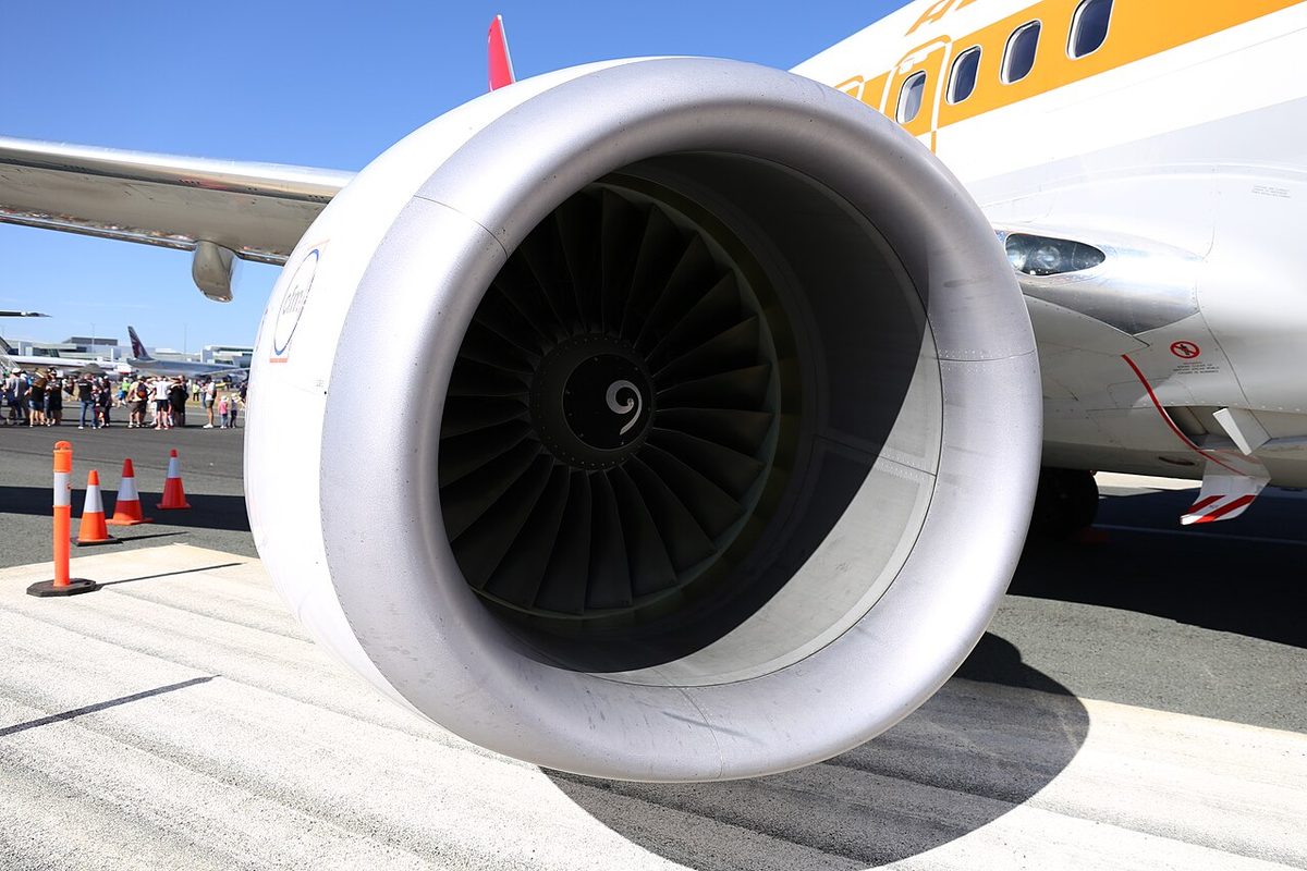
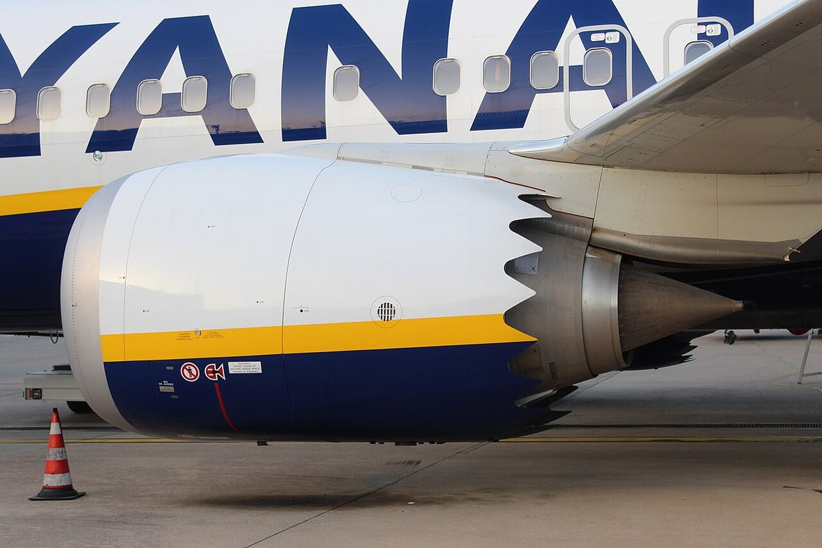
The Boeing 737 NG is powered by two CFM56-7B turbofans; the 737 MAX has the larger CFM LEAP-1B. Each engine has a full-authority digital electronic engine control (EEC) with two independent control channels, and thrust is set by fan speed, N1, in both of the EEC's control modes. Engine indications and most engine alerts appear on the display units of the common display system (CDS), with a few lights on the aft overhead panel.
This article follows the 737 NG flight crew operations manual (FCOM) and notes where the MAX differs. For the principles see FADEC and engine fuel control, gas turbine engine starting and thrust reversers and reverse thrust, and for thrust setting B737 autothrottle and thrust management.

- Engine control: EEC, MEC and PMC
- EEC normal and alternate modes
- Start switches, start levers and ignition
- Start protections and battery start
- Thrust reversers
- Primary and secondary engine indications
- Engine display formats and controls
- Engine alerts and exceedances
- Differences on the 737 MAX
- Frequently asked questions
Engine control: EEC, MEC and PMC
The EEC transfers automatically to its second channel if the operating channel fails, and it alternates between channels with each start or start attempt. It meters fuel through the engine's hydromechanical unit (HMU) and, in normal mode, compares commanded N1 with actual N1, adjusting fuel flow to close the gap. It provides N1 and N2 redline overspeed protection in both control modes but no EGT redline protection, so the crew must observe the EGT limits in every mode.
The EEC selects ground minimum, flight minimum and approach idle by itself. Approach idle, higher than flight minimum idle to shorten engine acceleration for a go-around, is selected in flight when cowl anti-ice is ON for either engine, or below 19,000 ft MSL with either main gear down and locked or the flaps at 15 or more. It holds until after touchdown, when ground minimum idle takes over.
Without EEC power, only N1, N2, oil quantity and vibration are displayed, directly from the engine sensors; the ENGINE START switch at GRD powers the EEC. The amber ENGINE CONTROL light, on the ENGINE panel of the aft overhead with the REVERSER lights and EEC switches, means the engine control system is not dispatchable because of faults; it works only with the engine running, on the ground below 80 kt before take-off or from about 30 seconds after touchdown.
The 737 Classic worked differently. ATPL instrumentation texts describe, for the 737-400, a hydromechanical main engine control (MEC) on each engine, trimmed electronically by a power management control (PMC) that holds the desired N1 without moving the lever, giving constant thrust through a climb. The PMC can be switched OFF, leaving the MEC alone in control of the engine.
EEC normal and alternate modes
With ON in view (white) on its EEC switch, on the aft overhead panel, each EEC is in normal mode: it calculates N1 thrust ratings from sensed flight conditions and bleed air demand. Full rated take-off thrust is reached at a thrust lever position short of the forward stop; maximum rated thrust is at the forward stop, where the EEC limits thrust according to the aeroplane model.
| Mode | Entered by | EEC switch | Thrust |
|---|---|---|---|
| Normal | Selected | ON | Ratings from sensed conditions, EEC limiting |
| Soft alternate | Automatic, normal-mode signals lost | ON and amber ALTN | Last valid flight conditions held |
| Hard alternate | Thrust lever to idle in soft alternate, or ALTN selected | ALTN; ON blanked if selected manually | Alternate schedule, no EEC limiting |
Soft alternate mode lets the change happen with no immediate change in thrust, but thrust rating shortfalls or exceedances may develop as ambient conditions change. It lasts until hard alternate mode is entered. In hard alternate the EEC uses the alternate mode thrust schedule, which always gives thrust equal to or greater than normal mode for the same lever position. With no EEC limiting, maximum rated thrust may come before full forward lever.
Warning: in hard alternate mode, the thrust levers go to or near full forward only when terrain contact is imminent, to avoid an overboost. With the EECs in normal mode, the NG's terrain avoidance recall allows full forward.
Start switches, start levers and ignition
Each ENGINE START switch has four positions:
- GRD uses battery power to open the start valve and close the engine bleed valve, arms the selected igniters for a ground start (both for an in-flight start), and is held by a solenoid until starter cutout;
- OFF: ignition normally off, though both igniters fire automatically with the start lever at IDLE if the EEC detects a flameout;
- CONT gives ignition to the selected igniters with the engine running and the start lever at IDLE, and to both in flight if N2 falls below idle;
- FLT gives ignition to both igniters with the start lever at IDLE.
On most variants each engine has two igniter plugs, the left powered from its AC transfer bus and the right from the AC standby bus. The ignition select switch (IGN L, BOTH, IGN R) chooses the igniters for both engines, IGN L and IGN R being alternated on successive starts. Ignition must be on for take-off, landing, heavy rain and anti-ice operation.
The engine start lever at IDLE energises the ignition through the EEC and electrically opens the spar fuel shutoff valve, in the wing leading edge outboard of the pylon, and the engine-mounted fuel shutoff valve. CUTOFF closes both valves and de-energises the ignition. Fuel reaches the engine only with both valves open, so the engine fire switch pulled also closes them.
The starter needs electrical power and bleed air from the APU, a ground cart or the other engine. With the switch at GRD, the amber START VALVE OPEN alert appears. The start lever goes to IDLE when N1 rotation is seen and N2 reaches 25 per cent or, failing that, at maximum motoring (N2 accelerating less than 1 per cent in about 5 seconds) with at least 20 per cent N2. Fuel flow indications lag by about two seconds, so EGT may rise first. At about 56 per cent N2 power is removed from the holding solenoid: the switch returns to OFF, the start valve closes and START VALVE OPEN goes out. The engine is stable at idle when the EGT start limit redline disappears, at about 59 per cent N2.
A start lever moved early, or a switch that drops out of GRD before cutout, can cause a hot start. An aborted engine start (hung start, no oil pressure by stable idle, no EGT rise within 15 seconds, EGT quickly nearing or exceeding the start limit) has one recall item: start lever to CUTOFF.
Start protections and battery start
Abnormal start protection works on ground starts only. The EEC watches for impending hot starts, engine stalls, EGT start limit exceedances and wet starts:
- an impending hot start or a stall makes the white box round the EGT readout flash, and current EEC software (7.B.Q and later) turns off ignition and fuel by itself;
- EGT above the start limit turns the EGT box and dial red and the EEC cuts ignition and fuel; after both engines are shut down the box turns red again as a reminder;
- if EGT does not rise after the lever reaches IDLE, the EEC cuts ignition and fuel 15 seconds later.
On a battery start with no AC power on the aeroplane, only N1, N2 and oil quantity are shown at first; the EEC is powered above 15 per cent N2, and every parameter then appears.
In flight an engine is restarted by windmilling or with crossbleed air; a magenta X-BLD above the N2 dial means airspeed is too low for a windmill start and crossbleed air is recommended.
Thrust reversers
Each engine has a hydraulic reverser of left and right translating sleeves: as they move aft, blocker doors deflect fan air forward through fixed cascade vanes. Systems A and B power the No. 1 and No. 2 reversers, the standby system being a slower alternate. Reverse is for ground use only, and the sleeves deploy only when either radio altimeter senses less than 10 ft or the air/ground sensor is in ground mode.
The reverse thrust lever can be raised only with its forward lever at idle, and raising it engages a locking pawl that holds the forward lever. It is blocked at reverse idle until the reverser is more than 60 per cent deployed. The REV indication is amber once the reverser leaves the stowed position and green when it is deployed; the lever can then go to detent No. 2, adequate for normal operations, or beyond it for maximum reverse. Moving it down past detent No. 1 commands the stow. Once the reverse levers have been moved, only a full stop landing can be made.
The amber REVERSER light comes on at each stow command and goes out about 10 seconds later, when the isolation valve closes. It also shows a valve or sleeve not in its commanded state, a fault in the synchronisation shaft lock circuitry or an auto-restow activation. The auto-restow circuit drives the sleeves back to stow after an incomplete stow or uncommanded movement towards deploy, and holds them there until a deploy command or maintenance action.
Primary and secondary engine indications
Red marks maximum and minimum limits and amber caution limits. The primary engine display carries N1, with the thrust mode display and reference N1 bugs, and EGT. EGT has red redlines for the maximum take-off limit and, when no start limit redline is shown, the in-flight start limit, an amber band starting at the maximum continuous limit, and, until stabilised idle, an EGT start limit redline. On most variants the EGT readout's change to amber is inhibited for up to 5 minutes during take-off or go-around.
The secondary engine indications, among them N2, oil pressure, oil temperature and vibration, appear automatically when the CDS is first powered, when an engine fails or a start lever goes to CUTOFF in flight, and when a secondary parameter leaves its normal range. The FUEL FLOW switch shows fuel flow (RATE, kg per hour x 1000) or fuel used (USED), or resets it (RESET). Indicated oil quantity can fall sharply during start, take-off and climb without any effect on the engine.
An inflight exceedance indication survives the flight: on the ground after shutdown, a red box round the N1 or N2 readout means a limit was exceeded in flight.
Engine display formats and controls
The primary engine display is normally on the upper display unit and the secondary on the lower. The MAIN PANEL DUs selector at INBD ENG PRI moves the primary display to the inboard unit; the LOWER DU selector at ENG PRI moves it to the lower unit and blanks the upper. If the upper unit fails, the primary display moves to the lower unit automatically, and if the secondary display is already there, a compact engine display results, with N2, oil pressure, oil temperature and vibration as digital readouts and any exceedance shown by a box outline in its colour, blinking for 10 seconds, then steady. On batteries alone, the engine indications remain on the upper display unit.
The engine display control panel carries the N1 SET and SPEED REFERENCE selectors, set to AUTO in the preflight, and the FUEL FLOW switch. ATPL instrumentation texts describe Boeing's EICAS, with a standby engine indicator; the 737 FCOM speaks instead of engine displays on the CDS, and its crew alerting relies on master caution lights and system annunciators.
Engine alerts and exceedances
| Alert (amber) | Meaning |
|---|---|
| ENG FAIL | Engine below sustainable idle (under 50 % N2) with its start lever at IDLE; stays until recovery, CUTOFF or fire switch pulled |
| START VALVE OPEN | Steady: start valve open, air to the starter. Blinking: uncommanded opening |
| LOW OIL PRESSURE | Oil pressure at or below the red line |
| OIL FILTER BYPASS | Impending bypass of the scavenge oil filter |
Blinking of the last three is inhibited on take-off from 80 kt to 400 ft RA (or 30 seconds after 80 kt, if sooner) and on landing from 200 ft RA to 30 seconds after touchdown; the alerts then show steady. A REVERSER light lasting more than about 12 seconds brings MASTER CAUTION and the ENG annunciator. For an engine limit exceedance, surge or stall, the recall items disengage the autothrottle and retard the thrust lever until the indications stabilise or the lever is closed.
Differences on the 737 MAX
The LEAP-1B is larger and more powerful than the CFM56-7B and sits higher and farther forward. The FSB grades the new engines Level B training and checking with a procedure change, and lists:
- an EEC without the overboost rating and with an added icing idle speed;
- a revised engine display, with no compact format, a new THRUST alert and a MOTORING indication for bowed rotor logic;
- REVERSER LIMITED in place of REVERSER, plus new REVERSER COMMAND and REVERSER AIR/GND alerts;
- an engine display control panel with an engine transfer switch and an MFD INFO switch.
The EASA type certificate data sheet gives 19.25 L of usable oil, against 10.3 L on the NG. Start figures, alert logic and the meaning of the forward stop should be learned from the MAX FCOM rather than carried over.
Frequently asked questions
What is the difference between soft and hard alternate mode on the 737 EEC?
Soft alternate is entered automatically when the signals the EEC needs for normal mode are lost. It keeps the last valid flight conditions, so thrust does not change at once, though shortfalls or exceedances can appear as conditions change. Hard alternate follows when the thrust lever is retarded to idle or ALTN is selected. It uses the alternate thrust schedule, always equal to or above normal thrust, with no EEC limiting, so an overboost is possible.
When is the engine start lever moved to IDLE on a 737 NG?
When N1 rotation is seen and N2 has reached 25 per cent. If 25 per cent cannot be reached, the lever goes to IDLE at maximum motoring, when N2 accelerates by less than 1 per cent in about 5 seconds, with at least 20 per cent N2. Moving it early can cause a hot start. The starter cuts out at about 56 per cent N2, when the ENGINE START switch returns to OFF.
What does the ENG FAIL alert mean on the Boeing 737?
The amber ENG FAIL alert appears when an engine is running below sustainable idle, less than 50 per cent N2, while its start lever is at IDLE. It stays until the engine recovers, the start lever is moved to CUTOFF or the engine fire switch is pulled. In flight, an engine failure or a start lever moved to CUTOFF also brings up the secondary engine indications automatically.
Why does the REVERSER light come on after every landing on the 737 NG?
The amber REVERSER light on the aft overhead panel comes on whenever a reverser is commanded to stow, and goes out about 10 seconds later when the isolation valve closes. That is normal. If it stays on for more than about 12 seconds, a malfunction has occurred and MASTER CAUTION and the ENG annunciator light. Pausing the reverse lever past detent No. 1 for about 16 seconds can engage the electro-mechanical lock.
What is the compact engine display on the 737 NG?
It is the format used when the primary and secondary engine indications must share one display unit, for example after an upper display unit failure with the secondary indications already on the lower unit. N2 changes from a round dial to digits, and oil pressure, oil temperature and vibration are shown as digital readouts only. An exceedance is shown by a box outline that blinks for 10 seconds. The 737 MAX has no compact format.
Test yourself on B737 Engines and Engine Indications
The v1prep banks cover this topic in the B737 type-rating bank, with a worked explanation for every answer. EASA ATPL, PPL, IR and CPL, the FAA written tests and A320/B737 type ratings.
Start practising →Sources and further reading
- EASA Type Certificate Data Sheet IM.A.120, Boeing 737
- FAA Flight Standardization Board Report, Boeing 737
- EASA Easy Access Rules for Large Aeroplanes (CS-25), powerplant instruments and markings
- 14 CFR 25.933, Reversing systems
- FAA Aviation Maintenance Technician Handbook, Powerplant (FAA-H-8083-32B)
- EASA, Explanatory Note to ED Decision 2018/001/R, Part-FCL theoretical knowledge learning objectives (021 Powerplant)
Library articles are written for study and exam preparation. They do not replace your aircraft's approved documentation, your operator's procedures or the regulations themselves.