Aerodrome Lighting and Visual Aids
Aerodrome lighting is the system of beacons, approach lights, visual approach slope indicators, runway lights and taxiway lights that guides pilots to and on an aerodrome at night and in poor visibility, using colours, patterns and intensities standardised by ICAO Annex 14 and, in the United States, the FAA.
At night and in low visibility an aerodrome is known by its lights. They lead the pilot from the approach to the threshold, show the approach slope, outline the runway, count down the distance remaining, and then guide the aircraft along the taxiways and stop it short of any runway it has not been cleared to enter. Each light's colour, pattern and direction is standardised, so the same picture means the same thing at any aerodrome.
Colour carries the meaning. Green marks the way in: the threshold and the taxiway centre line. Red marks the limit of what may be used: the runway end, the stopway, the stop bar. White belongs to the runway and the approach, turning yellow or red as the runway runs out. Blue marks taxiway edges and yellow a caution or a holding point. The standards are in ICAO Annex 14; the FAA's, described in chapter 2 of the AIM, are similar, with differences noted below. What each AIP lists for a runway is shown by the Lyon Saint-Exupéry entry for runway 35L: a Category III approach lighting system 900 m long, a PAPI set at 3.0° with a minimum eye height over the threshold (MEHT) of 59 ft, touchdown zone lights over 900 m, centre line lights every 15 m, and edge lights every 60 m, the last 600 m yellow.

Aerodrome and identification beacons
An aerodrome beacon helps pilots find an aerodrome at night. Annex 14 provides one at aerodromes used at night where aircraft navigate mainly visually, where reduced visibility is frequent, or where the aerodrome is hard to locate from the air. At a land aerodrome it shows white flashes, or white alternating with green; at a water aerodrome, white or white alternating with yellow. The EU rules require a beacon only at aerodromes with night VFR traffic and do not impose the colour of the flashes that alternate with the white.
An identification beacon, used where an aerodrome cannot easily be identified from the air by other means, flashes the aerodrome's identification in Morse code: green at a civil land aerodrome, yellow at a water aerodrome, and red at UK military aerodromes. Some identification beacons already installed in France flash white instead of green.
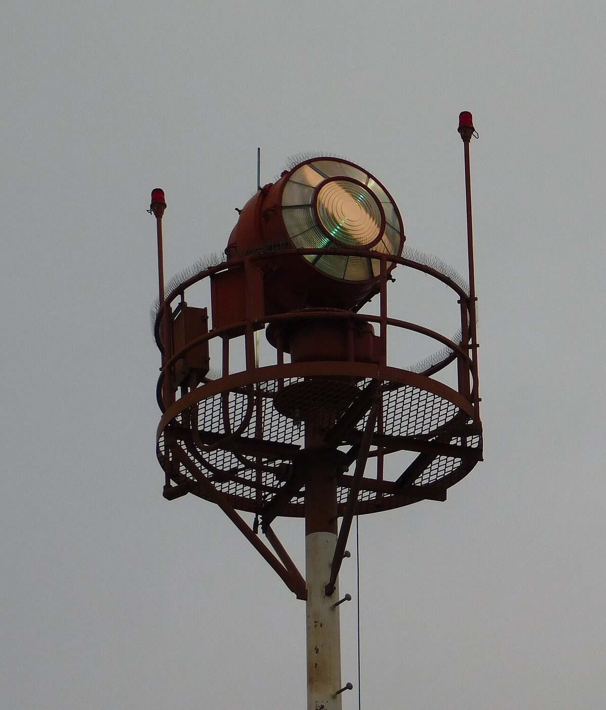
The FAA's airport rotating beacon gives 24 to 30 flashes a minute, 30 to 45 at heliports. Civil land airports show white and green, water airports white and yellow, heliports green, yellow and white, and military airports two quick white flashes between the green. In Class B, C, D and E surface areas a beacon operating by day often means that the ground visibility is below 3 miles or the ceiling below 1,000 ft, but many beacons are switched by photocells, so the pilot confirms the weather instead of relying on the beacon.
Approach lighting systems
An approach lighting system (ALS) extends the runway centre line into the approach so that the pilot of an instrument approach can pick up the runway alignment before the runway itself is visible.
- A simple approach lighting system, for non-instrument and non-precision runways, is a row of lights on the extended centre line reaching not less than 420 m from the threshold, with a crossbar 18 m or 30 m long at 300 m.
- A precision approach Category I lighting system extends, wherever possible, 900 m from the threshold, with a crossbar at 300 m. The length is chosen to give guidance from about Category I minima on a 3° approach. The centre line is formed either of barrettes, groups of three or more lights close together that look like a short bar, or of single lights, in which case further crossbars are added at 150, 450, 600 and 750 m.
- The Calvert system, used in the UK and elsewhere, has five crossbars and a distance-coded centre line; a NATO variant omits the distance coding. Lyon's approach lights are also described as a distance-coded centre line.
- Category II and III systems add lights over the last part of the approach, nearest the threshold: the Lyon AIP describes a Category II reinforcement in the last metres, and the FAA's ALSF-2 adds red side row bars (see below).
- Lead-in lights (LDIN) guide aircraft along a curved or straight path to the point where the approach lights come into view. They are groups of at least three flashing white lights, ideally flashing in sequence towards the runway.
In the United States, approach lights extend 2,400 to 3,000 ft on precision runways and 1,400 to 1,500 ft on non-precision runways. Some include sequenced flashing lights, which appear as a ball of light running towards the runway twice a second. On the ALSF-1 and ALSF-2 systems, red terminating bars or red side row bars mark the last 1,000 ft before the threshold.
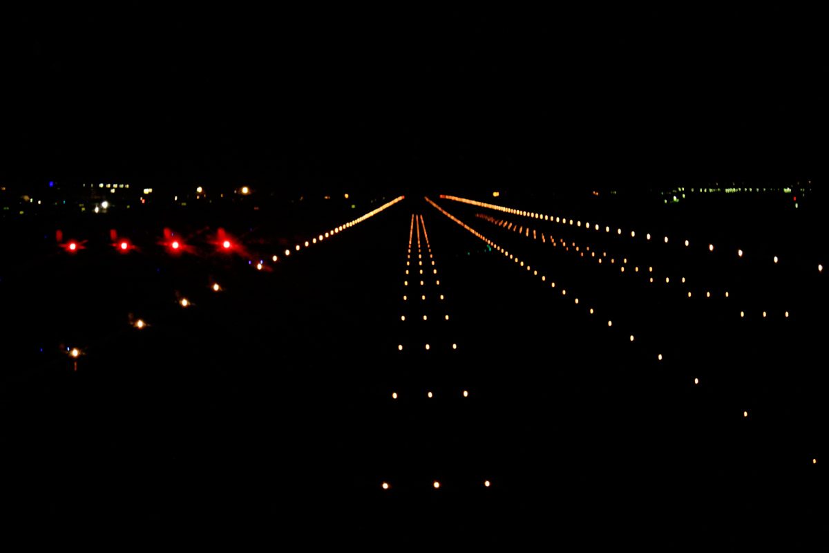
The approach lights are also a visual reference for continuing below decision altitude. Under EASA rules identifiable elements of the approach lighting qualify at a Category I decision height, provided further references then appear. Under 14 CFR 91.175, the approach lights alone allow descent only to 100 ft above the touchdown zone elevation, unless the red terminating bars or red side row bars are distinctly visible. Inoperative approach lights raise the visibility minima (see aerodrome operating minima).
Visual approach slope indicators
A visual approach slope indicator shows the pilot whether the aircraft is on, above or below a defined approach slope. The FAA calls the family visual glide slope indicators (VGSI).
The precision approach path indicator (PAPI) is a wing bar of four light units, normally on the left of the runway. Each unit shows white above its setting angle and red below it, and the unit nearest the runway has the highest setting:
| PAPI shows | Position |
|---|---|
| Four white | Well above the slope |
| Three white, one red | Slightly above |
| Two white, two red | On the slope |
| One white, three red | Slightly below |
| Four red | Well below |
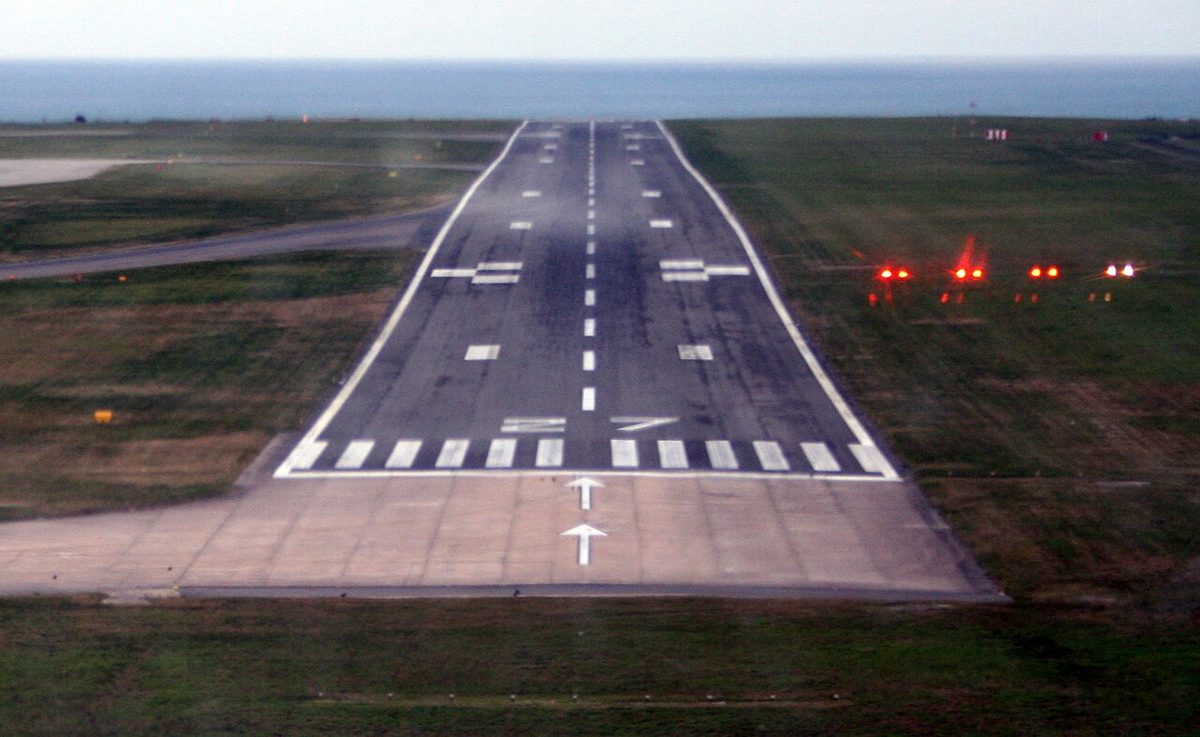
The abbreviated PAPI (APAPI) has only two units: one red and one white is on the slope, two white above, two red below. The slope is usually 3°, but obstacles or terrain can require more: Nice's runway 22 PAPIs are set at 3.2°, and the PAPI for Chambéry's runway 18 at 4.5°. Charts give the minimum eye height over the threshold (MEHT), the lowest height of the pilot's eye above the threshold when on the PAPI slope, not a decision height. The PAPI gives no lateral guidance, which comes from the runway and its lights, and descent on it should not begin until the aircraft is aligned with the runway.
The older VASI has two wing bars, a near and a far bar, each white in the upper part of its beam and red in the lower. Near white and far red is on the slope, both white is high and both red is low. Three-bar VASIs give a second, higher slope for aircraft with high cockpits. The FAA also describes tri-colour and pulsating indicators. T-VASIS and its abbreviated form AT-VASIS are still found at some aerodromes, but ICAO recommended phasing them out as standard systems from 1 January 2020, and France does not allow them. The FAA says a PAPI is visible from about 5 miles by day and 20 by night and gives obstacle clearance within 10° of the centre line to 3.4 NM.
Threshold, wing bar and runway end lights
Runway threshold lights are fixed, unidirectional green lights showing towards the approach, in a row across the runway as near to its end as possible. At a displaced threshold they mark the new threshold, often in the form of wing bars, green barrettes either side of the runway, and the runway edge lights between the runway end and the displaced threshold show red towards the approach.
Runway threshold identification lights (RTIL) are unidirectional white flashing lights at the threshold, used on a non-precision runway that needs more conspicuity or where the threshold is permanently displaced. The FAA's runway end identifier lights (REIL) are a pair of synchronised flashing lights, one on each side of the threshold.
Runway end lights are fixed, unidirectional red lights, at least six, showing along the runway towards an aircraft taking off or landing. In the United States the lights marking each runway end show green outwards, to landing aircraft, and red towards the runway.
Runway edge, centre line and touchdown zone lights
Runway edge lights are fixed white lights of variable intensity in two parallel rows along the full length, visible in both directions of use. Over the last 600 m or last third of the runway, whichever is less, they may show yellow as a caution zone. The FAA classifies edge lights as high, medium or low intensity (HIRL, MIRL and LIRL), and its caution zone on instrument runways covers the last 2,000 ft or half the runway, whichever is less.
Runway centre line lights are required on Category II and III runways and on runways used for take-off below an RVR of the order of 400 m, and recommended on Category I runways, particularly where the edge lights are more than 50 m apart. They are white, then alternate red and white from 900 m to 300 m before the runway end, then all red for the last 300 m. The FAA's runway centerline lighting system (RCLS) uses lights every 50 ft, white until the last 3,000 ft, then alternating red and white for 2,000 ft, then all red over the last 1,000 ft.
The touchdown zone is the part of the runway beyond the threshold where landing aeroplanes are intended first to touch down. Touchdown zone lights (TDZL), two rows of white barrettes, one on each side of the centre line, mark the touchdown zone of Category II and III runways, extending 900 m from the threshold on runways of 1,800 m or more. The FAA's extend from 100 ft beyond the threshold to 3,000 ft or the runway midpoint, whichever is less.
Stopway lights, along a stopway used at night, are fixed, unidirectional red lights showing towards the runway.
Taxiway lighting
Taxiway edge lights are fixed, omnidirectional blue lights. Taxiway centre line lights are fixed green lights, visible only to aircraft on or near the taxiway, and are provided where taxiways are used in RVR below 350 m. Where a taxiway crosses the ILS critical or sensitive area, and on high-speed exits, they alternate green and yellow, so a pilot leaving the runway knows it is clear only after the last yellow light. The FAA uses the same colours for its lead-off and lead-on lights.
Holding points have their own lights. Intermediate holding position lights are three fixed, unidirectional yellow lights across the taxiway. The FAA's clearance bar is three in-pavement steady yellow lights at a holding position.
Stop bars and runway guard lights
A stop bar is a row of red lights across the taxiway at a runway-holding position, showing towards taxiing aircraft. An aircraft stops at a lit stop bar and proceeds only when the lights are switched off and it holds a clearance. Annex 14 requires stop bars at runway-holding positions serving a runway used in RVR below 550 m, unless other aids and procedures prevent incursions. The FAA uses them below 1,200 ft RVR and warns never to cross a lit stop bar, even if cleared. Lyon's AIP entry distinguishes remote-controlled and permanent stop bars, and adds red no-entry bars, lit day and night, across taxiways that may not be used to enter the runway; French national rules require stop bars only for Category II and III operations and take-offs below 150 m RVR.
Runway guard lights (RGL), nicknamed wig-wags, are flashing yellow lights warning of a runway ahead: a pair beside the taxiway or a row across it. Annex 14 provides them at runway entrances used in RVR below 550 m where there is no stop bar, and in RVR between 550 m and 1,200 m where traffic is heavy. Places where incursions are likely are also marked as hot spots on aerodrome charts (see aerodrome markings and signs).
Some US airports add runway status lights (RWSL): red in-pavement runway entrance lights and takeoff hold lights switched automatically by surveillance data when a runway is unsafe to enter or take off from. They never replace a clearance.
Control of aerodrome lighting
Lights may be switched off when not needed, provided they can be switched on again within one hour. At selected US airports, often those without an operating tower, pilot-controlled lighting is switched from the air: seven microphone clicks within five seconds for the highest intensity, five for medium, three for the lowest, the lights staying on for 15 minutes from the last activation. Obstacles are lit separately (see obstacles and obstacle limitation surfaces).
Frequently asked questions
How do you read a PAPI?
A PAPI is a row of four light units beside the runway, normally on the left. Each unit shows white above its setting angle and red below it. Two red and two white means on the approach slope; three white and one red slightly above; four white well above; three red and one white slightly below; four red well below. An APAPI has only two units, and one red with one white is on the slope.
Why do runway centre line lights turn red?
They tell a pilot on the landing roll or take-off run how much runway is left. Under ICAO Annex 14 they are white for most of the runway, alternate red and white from 900 m to 300 m before the end, and are all red for the last 300 m. The FAA pattern is the same in feet, alternating from 3,000 ft to 1,000 ft before the end and all red for the last 1,000 ft.
What colour is an airport beacon?
Under ICAO Annex 14 an aerodrome beacon at a land aerodrome shows white flashes, or white flashes alternating with green; at a water aerodrome white alternates with yellow. An identification beacon flashes the aerodrome's Morse identification in green. In the United States civil land airports use white and green, heliports green, yellow and white, and military airports two quick white flashes between the green ones.
What is a stop bar at an airport?
A stop bar is a row of red lights across a taxiway at a runway-holding position, showing towards taxiing aircraft. When it is lit, the aircraft stops and waits; it may proceed only when the lights are switched off and it has a clearance. ICAO requires stop bars at holding positions serving runways used in RVR below 550 m, unless other aids or procedures prevent incursions. The FAA says never to cross a lit stop bar, even if cleared.
How does pilot-controlled lighting work?
At many US airports without an operating tower the pilot turns the lights on by keying the microphone on a published frequency. Seven clicks within five seconds give the highest intensity available, five a medium or lower setting and three the lowest. The lights stay on for 15 minutes from the last activation, so the AIM recommends keying seven times first and again when entering the final approach.
Test yourself on Aerodrome Lighting and Visual Aids
The v1prep banks cover this topic in Air Law (010), with a worked explanation for every answer. EASA ATPL, PPL, IR and CPL, the FAA written tests and A320/B737 type ratings.
Start practising →Sources and further reading
- ICAO Annex 14, Aerodromes, Volume I, Aerodrome Design and Operations
- FAA Aeronautical Information Manual, Chapter 2 Section 1, Airport Lighting Aids
- 14 CFR 91.175, Takeoff and landing under IFR
- AIP France, AD 2 LFLL, Lyon Saint-Exupéry (AD 2.14, approach and runway lighting)
- AIP France, GEN 1.7, Differences from ICAO Standards, Recommended Practices and Procedures (Annex 14, chapter 5)
Library articles are written for study and exam preparation. They do not replace your aircraft's approved documentation, your operator's procedures or the regulations themselves.