Instrument Landing System (ILS)
The instrument landing system (ILS) is a ground-based precision approach aid in which a VHF localiser gives lateral guidance and a UHF glide path gives vertical guidance along a fixed straight-in path to the runway, allowing approaches down to a decision height or, with suitable equipment, to touchdown.
The ILS (instrument landing system) is the standard ground-based precision approach aid. Two radio signals radiated from beside the runway give the pilot, or the autopilot, lateral and vertical guidance along a fixed straight-in path to a decision height and, at suitably equipped runways, to touchdown and roll-out. Both signals are angular, so the guidance tightens as the aircraft nears the runway, which is why the ILS supports the lowest landing minima in use.
ICAO Annex 10, Volume I, standardises the system, so most figures are common to EASA and FAA exams. The vocabulary differs: ICAO and EASA say glide path and, in British usage, localiser; the FAA says glide slope and localizer, quotes runway visual range (RVR) in feet and still subdivides Category III. RNP approaches with vertical guidance are replacing some installations, but the ILS remains the yardstick.
ILS components and layout
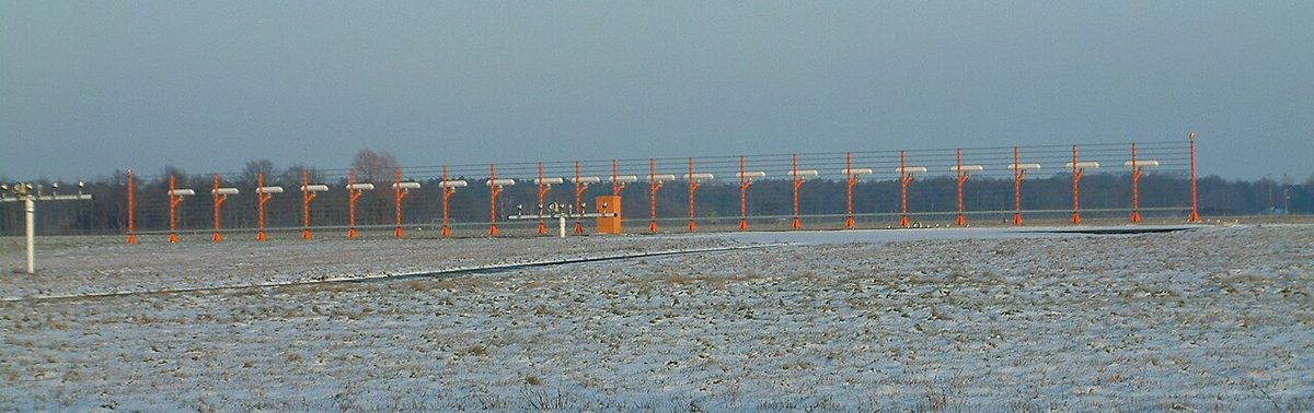
- The localizer (LOC), written localiser in British usage, gives lateral guidance from an antenna array beyond the stop end of the runway, on the extended centreline.
- The glide path (GP), called the glide slope (GS) by the FAA and on most displays, gives vertical guidance from an antenna mast beside the runway, abeam the touchdown zone.
- Marker beacons or, more often today, a DME give distance checks.
- Monitors switch to a standby transmitter or shut the facility down if a signal strays beyond limits, so the crew gets no guidance rather than wrong guidance.
| Component | Band | Channels | Position |
|---|---|---|---|
| Localiser | VHF, 108 to 111.975 MHz | 108.10 to 111.95 MHz, odd tenths | Beyond the stop end, on the centreline |
| Glide path | UHF, 328.6 to 335.4 MHz | 329.15 to 335.00 MHz, paired | Beside the runway, abeam touchdown |
| Marker beacons | 75 MHz | One frequency for all | On the extended centreline |
The 40 localiser channels use odd tenths, including 50 kHz steps (108.10, 108.15, 108.30), leaving even tenths to VORs. Pairing means the pilot tunes only the localiser. The Morse identifier is sent on the localiser frequency; in the United States it is the letter I followed by three letters.
The localiser
The localiser radiates two overlapping patterns carrying tones of 90 Hz and 150 Hz. To a pilot approaching the runway, 90 Hz predominates left of the centreline and 150 Hz to the right; on the centreline neither does.
The course width is tailored to the runway: typically 3° to 6° in total, so that the sector measures about 700 ft (210 m) across at the threshold. With full scale typically about 2.5° either side, the localiser is roughly four times as sensitive as a VOR.
ICAO requires coverage to 25 NM within 10° of the course line, 17 NM between 10° and 35°, and 10 NM beyond 35° where that coverage is provided. The FAA promises less: correct indications to 18 NM within 10°, and to 10 NM between 10° and 35°. Outside coverage the needle can look convincing and still be wrong. The FAA does not authorise holding below 5,000 ft between the outer marker and the airport, because aircraft there disturb the signal.
Exam tip: a receiver detecting mainly 90 Hz on both localiser and glide path is left of the centreline and above the path. On an inbound QDM of 264°, left of track means south of the localiser.
The glide path and reference datum
The glide path works the same way in the vertical plane: 90 Hz predominates above the path and 150 Hz below it. The path is formed by the direct signal combining with its reflection from the flat ground in front of the antenna.
The glide path angle is the angle that the mean glide path, taken as a straight line, makes with the horizontal. The approach glide path angle is the value published for the procedure, for example "GP 3.0°". PANS-OPS treats 3° as optimum and classes any path steeper than 3.5°, or with a nominal descent rate above 1,000 ft/min, as non-standard. A 3° path descends about 318 ft per NM, a 5.2% gradient, so the descent rate in ft/min is about five times the groundspeed in knots: roughly 740 ft/min at 140 kt.
ICAO requires glide path coverage 8° either side of the centreline to at least 10 NM, vertically from 0.45θ to 1.75θ, where θ is the glide path angle (1.35° to 5.25° for a 3° path).
Near the ground the path bends, so its geometry is fixed by the ILS reference datum point: a point directly above where the runway centreline crosses the threshold, through which the straight part of the glide path would pass if extended downwards. Annex 10 sets its height at 15 m (50 ft), with a tolerance of plus 3 m (10 ft). FAA charts publish the equivalent as the threshold crossing height (TCH), the height of the aircraft's glide slope antenna over the threshold on the path. The wheels cross lower, by a margin that grows with aircraft size.
The glideslope intercept altitude is the published altitude at which an aircraft established on the localiser meets the glide slope, marked on FAA charts by a lightning-bolt symbol. That point is the final approach fix of the precision approach; ICAO calls it the final approach point (FAP). Crossing the fix at the charted altitude is a gross check of the altimeter setting and the glide path. If the glide path fails, the approach may continue as a localiser-only non-precision approach to higher minima.
Difference in depth of modulation and deviation display
The receiver measures the difference in depth of modulation (DDM): the modulation depth of the stronger tone minus that of the weaker, expressed as a fraction. It is zero on the course line and on the path and grows in proportion to angular displacement, so the needle shows angle, not distance.
| Quantity | Localiser | Glide path |
|---|---|---|
| Predominant tone | 90 Hz left, 150 Hz right | 90 Hz above, 150 Hz below |
| Modulation depth of each tone on course | 20% | 40% |
| Edge of half-sector | 0.155 DDM, about 105 m (350 ft) either side at the threshold | 0.0875 DDM at 0.12θ, about 0.36° on a 3° path |
The localiser's nominal sensitivity is 0.00145 DDM per metre at the reference datum. Beyond the sector ICAO requires the DDM to stay at or above 0.155, so the needle stays pinned towards the correct side.
An ILS deviation dot is one division of the deviation scale. Most electronic displays use two dots each side, with full scale at the localiser sector edge; on the glide path one dot is 0.0875 DDM, so two dots are about 0.7° on a 3° path, matching the FAA's description of a beam 1.4° thick. Because the scale is angular, one dot below the glide path means about 190 ft at 5 NM but only about 40 ft at 1 NM. A flag or the removal of the scale warns of an invalid signal. Stabilised approach criteria typically allow no more than one dot, and GPWS Mode 5 calls "GLIDESLOPE" when the aircraft sinks well below the path (see GPWS and TAWS).

Marker beacons and locators
A marker beacon is a low-power 75 MHz transmitter radiating a narrow fan-shaped beam upwards. Passing over it lights a lamp and sounds a keyed tone.
| Marker | Tone | Keying | Light | Typical position |
|---|---|---|---|---|
| Outer marker (OM) | 400 Hz | Dashes | Blue | 4 to 7 NM out, near the glide path intercept |
| Middle marker (MM) | 1,300 Hz | Alternate dots and dashes | Amber | About 3,500 ft from the threshold, near the CAT I decision height |
| Inner marker (IM) | 3,000 Hz | Dots | White | Between the MM and the threshold, near the CAT II decision height |
A compass locator is a low-powered NDB sited at a marker; in the United States it is typically under 25 W, works between 190 and 535 kHz and reaches at least 15 miles. At the outer marker it forms a locator outer marker (LOM), which transmits the first two letters of the localiser identifier; a middle locator sends the last two. Many markers have been withdrawn in favour of DME distances or RNAV fixes. Older rules, still reflected in some exam questions, used the outer marker or equivalent position as the gate for the approach ban (see aerodrome operating minima).
Critical and sensitive areas
Vehicles and aircraft near the antennas reflect or block the signals, so ILS critical and sensitive areas are defined around both.
- The ILS critical area is the zone nearest the antennas, from which ICAO requires vehicles, including aircraft, to be "excluded during all ILS operations".
- The ILS sensitive area surrounds it. Movement and parking there are controlled, above all in low visibility, when an aircraft taxiing or taking off could disturb the guidance of one on short final or rolling out on autoland.
Hence the CAT II/III holding points further from the runway, the taxiway centreline lights alternating green and yellow across the protected zone, and the wider spacing between arrivals in low-visibility operations.
The FAA protects the areas when the reported ceiling is below 800 ft or the visibility below 2 miles and an arriving aircraft is inside the outer marker or final approach fix. In better weather they are unprotected, so a crew planning an autoland, or intending to use SA CAT I, CAT II or CAT III minima, must tell the tower.
Warning: an autoland in good weather may be flown with the areas unprotected. Be ready to disconnect if the aircraft deviates as other traffic passes the antennas.
False glide slopes and intercepting from below
The glide path pattern contains further nulls above the real path. The first false glide slope lies near twice the path angle, about 6° for a 3° path, and senses in reverse. The next, near 9°, senses normally but would demand three times the normal descent rate. None lies below the published path, and the FAA's AIM warns of false courses and reverse sensing at angles well above it.
Hence the standard technique: establish on the localiser, then intercept the glide path from below at the published intercept altitude. A descent rate far above five times the groundspeed, or an altitude that disagrees with the chart at a DME fix, points to a false path or an altimeter error.
Capture from above is not harmless. In May 2013 a Boeing 737 approaching Eindhoven was on the localiser and above the glide path in approach mode. On glide slope capture it pitched up steeply, far beyond a normal attitude, and the stick shaker activated before the crew recovered. The Dutch Safety Board found the signal above the path poorly understood, the belief that a false glide slope still leads to the runway mistaken, and similar events elsewhere between 2011 and 2013.
ILS categories I, II and III
The ILS categories (I / II / III) exist at two levels. The facility performance category describes the ground equipment: Category I gives guidance down to 200 ft or less, Category II to 50 ft or less, and Category III, with ancillary equipment where necessary, to and along the runway surface. States also publish a classification such as III/E/4: facility category, the point to which the localiser meets the tighter course structure (D is 3,000 ft beyond the threshold, E 2,000 ft before the runway end), and an integrity and continuity level from 1 to 4.
The operation category is what the crew may fly; the most limiting of facility, aircraft certification, crew qualification, lighting and aerodrome procedures sets it.
| Category | Decision height | ICAO / EASA RVR | FAA RVR |
|---|---|---|---|
| CAT I | 200 ft or above | 550 m or more (ICAO: or visibility 800 m) | 1,800 ft or more (2,400 ft without touchdown zone and centreline lights) |
| CAT II | Below 200 ft, not below 100 ft | 300 m or more | 1,200 ft or more (1,000 ft with autoland or HUD to touchdown and approval) |
| CAT III | Below 100 ft, or none | Below 300 m, or no limit | IIIa 700 ft, IIIb 150 ft, IIIc no limit |
EASA's all-weather operations rules, applicable from 30 October 2022, dropped the CAT IIIA/IIIB/IIIC subdivision, and the lowest RVR for a decision height between 50 ft and 100 ft fell from 200 m to 175 m, in line with ICAO. Operational credits such as SA CAT I allow a decision height down to 150 ft and an RVR down to 400 m. Anything below standard CAT I needs specific approval: under Part-SPA (SPA.LVO) in Europe, operations specifications C059 and C060 for FAA air carriers. For CAT II and III the decision height is read from the radio altimeter, and the lowest minima rely on autoland or head-up guidance.
Exam tip: many question banks still use older JAR-OPS/EU-OPS figures: CAT IIIA with a decision height below 100 ft and an RVR of at least 200 m, and CAT IIIB with a decision height below 50 ft or none and an RVR below 200 m but not less than 75 m.
Frequently asked questions
What frequencies does an ILS use?
ICAO allocates the localiser the band 108 to 111.975 MHz, with 40 channels from 108.10 to 111.95 MHz on odd tenths, such as 108.10 and 108.15; VORs in the same band use even tenths. The glide path works in the UHF band 328.6 to 335.4 MHz, with channels from 329.15 to 335.00 MHz, each paired with a localiser channel, so tuning the localiser also tunes the glide path. Marker beacons all transmit on 75 MHz.
Why should the ILS glide slope be intercepted from below?
The glide path antenna produces extra nulls above the true path, at about twice the angle with reversed sensing and at three times the angle with normal sensing. None exist below the published path. Intercepting from below, at the published intercept altitude after establishing on the localiser, guarantees the first null met is the real one. Capturing from above has caused sudden autopilot pitch-ups.
What is the difference between the ILS critical area and the sensitive area?
The critical area is the zone closest to the localiser and glide path antennas where any vehicle or aircraft would unacceptably distort the signal, so ICAO excludes them during all ILS operations. The sensitive area is larger and surrounds it; movement and parking there are controlled when protection is needed, typically under low-visibility procedures, which is why aircraft then hold further from the runway.
What are the CAT I, CAT II and CAT III ILS minima?
Under ICAO and EASA definitions, CAT I has a decision height of at least 200 ft and an RVR of at least 550 m. CAT II has a decision height below 200 ft but not below 100 ft and an RVR of at least 300 m. CAT III has a decision height below 100 ft or none, and an RVR below 300 m. The FAA quotes RVR in feet and still divides CAT III into IIIa, IIIb and IIIc.
What is the ILS reference datum?
It is a point directly above where the runway centreline crosses the threshold, through which the straight part of the glide path would pass if extended downwards. ICAO sets its height at 15 m (50 ft), with a tolerance of plus 3 m (10 ft). The FAA publishes the equivalent figure on approach charts as the threshold crossing height (TCH) of the glide slope.
Test yourself on Instrument Landing System (ILS)
The v1prep banks cover this topic in General and Radio Navigation (061/062), with a worked explanation for every answer. EASA ATPL, PPL, IR and CPL, the FAA written tests and A320/B737 type ratings.
Start practising →Sources and further reading
- ICAO Annex 10, Aeronautical Telecommunications, Volume I, Radio Navigation Aids (copy published by IACM Mozambique)
- FAA Aeronautical Information Manual, Chapter 1 Section 1 (1-1-9, Instrument Landing System)
- FAA Pilot/Controller Glossary, I (ILS categories)
- EASA, Explanatory Note to ED Decision 2022/012/R, All-weather operations
- ICAO EUR Doc 040, European Guidance Material on Management of ILS Critical and Sensitive Areas
- Dutch Safety Board, Pitch-up Upsets due to ILS False Glide Slope
- Qatar AIS, AIC 01/2024, ILS Facility Classification
Library articles are written for study and exam preparation. They do not replace your aircraft's approved documentation, your operator's procedures or the regulations themselves.