Obstacles and Obstacle Limitation Surfaces
An obstacle is any fixed or mobile object that stands where aircraft move on the ground or rises into airspace that must be protected for aircraft in flight. Obstacle limitation surfaces are the imaginary surfaces around a runway that define the airspace to be kept free of obstacles.
An obstacle is anything an aircraft could hit: a building, a mast, a crane, a power line, a wind turbine, but also a vehicle on the apron or a light fitting beside the runway. Terrain is dealt with separately, through minimum altitudes and terrain charts; this article is about the man-made objects, fixed or mobile, that rise from it.
Obstacles are managed in three ways. Around aerodromes, ICAO Annex 14 defines obstacle limitation surfaces (OLS) that mark the airspace to be kept free of them. What cannot be removed is surveyed, published and made conspicuous by marking and lighting. And close to runways and taxiways, where some equipment has to stand, it is made frangible, so that an aircraft that strikes it suffers as little damage as possible. Pilots meet the results in every AIP entry, obstacle chart, departure procedure and performance calculation.
Aerodrome and en-route obstacles
Annex 14 distinguishes two kinds of obstacle by where they stand:
- an aerodrome obstacle is one that penetrates the obstacle identification surface out to 15 km from the aerodrome;
- beyond 15 km, an object is normally treated as an en-route obstacle, an obstacle to aircraft in flight, only if it is more than 150 m high. Lower objects may still count if they are prominent and stand on or near routes regularly used by helicopters.
Aerodrome obstacles are published with the aerodrome. In AIP AD 2.10 each State lists them, often by reference to charts: the Lyon Saint-Exupéry entry points to the aerodrome chart and the obstacle charts, and offers electronic terrain and obstacle data. The aerodrome obstacle chart, ICAO Type A, shows the obstacles in the take-off flight path area that operators need for their performance calculations (see aeronautical charts).
On visual charts, the figure beside an obstacle symbol gives the elevation of its top. A French visual approach chart shows a mast at a Toulouse reporting point marked 1106: its top is at 1,106 ft AMSL, so an aircraft crossing at 2,000 ft clears it by about 900 ft. FAA sectional charts give the elevation of the top above mean sea level with the height above ground in brackets, and flash marks around the symbol show high-intensity obstacle lights. Obstacles that appear at short notice, such as a crane erected near the approach path, are published by NOTAM (see aeronautical information services).
Obstacle limitation surfaces
The obstacle limitation surfaces are imaginary surfaces, defined in chapter 4 of Annex 14, that together describe the airspace around a runway to be kept free of obstacles. Their purpose is twofold: to let aircraft approach, land, go around, take off and circle safely, and to stop the aerodrome being made unusable as buildings and masts grow around it. Their dimensions and slopes depend on the runway code number and on whether the runway is a non-instrument, non-precision or precision approach runway (see aerodrome physical characteristics). Amendment 18 to Annex 14, adopted in 2025, replaces them with a new framework of obstacle free surfaces and obstacle evaluation surfaces, applicable from 21 November 2030; until then the surfaces described here remain the standard.
The principal surfaces are:
- the approach surface, an inclined plane rising outwards from before the threshold, which protects the final approach;
- the transitional surfaces, sloping up and outwards from the sides of the runway strip and part of the approach surface, which limit the height of objects beside the runway;
- the inner horizontal surface, a horizontal plane above the aerodrome and its surroundings, which protects visual circling;
- the conical surface, sloping up and outwards from the edge of the inner horizontal surface;
- the take-off climb surface, an inclined plane beyond the end of the runway or clearway, which protects the initial climb;
- for precision approach runways, the inner approach, inner transitional and balked landing surfaces, which protect the last part of the approach and a go-around from low height.
The inner approach, inner transitional and balked landing surfaces together bound the obstacle free zone (OFZ) close to a precision approach runway, which is kept clear of fixed objects other than light, frangible ones that must be there for air navigation. France, for example, notes in GEN 1.7 that its national rules allow some obstacles to penetrate the OFZ of a Category I runway in very particular cases, subject to a safety study and, where needed, operational restrictions.
When an object penetrates a surface, the aerodrome operator has three choices: remove it, mark and light it, or restrict operations to allow for it. Displacing a landing threshold is a common answer to an obstacle on the approach, which is why the paved runway before a displaced threshold may be used for take-off but not for touchdown.
Obstacles and flight procedures
The OLS belong to the aerodrome. Instrument procedures are protected separately by the procedure designer, who assesses the obstacles against the surfaces of PANS-OPS or, in the United States, TERPS (see obstacle clearance and approach minima).
- Departures. A PANS-OPS departure assumes a climb gradient of at least 3.3 per cent; a steeper gradient is published only when an obstacle requires it, together with the controlling obstacle. In the United States, obstacles are assessed against a 40:1 obstacle identification surface that starts at the departure end of the runway and rises at 152 ft per NM, and the standard departure assumes a crossing height of at least 35 ft at the runway end and a climb of at least 200 ft per NM. Obstacles that penetrate the surface are listed as takeoff obstacle notes (see instrument departures).
- Missed approaches. PANS-OPS checks missed approach obstacle clearance with a 2.5 per cent climb gradient, and where a steeper gradient gives lower minima, both are published.
- Performance. The net take-off flight path of a performance class A aeroplane must clear every obstacle in the take-off flight path by at least 35 ft, or 50 ft where the aeroplane is banked by more than 15° (see takeoff flight path and obstacle clearance).
- Minimum heights. Under the rules of the air, a VFR flight over a congested area stays at least 1,000 ft above the highest obstacle within 600 m, and an IFR flight at least 1,000 ft above the highest obstacle within 8 km of its estimated position, or 2,000 ft over high or mountainous terrain (see minimum safe altitudes).
Marking of obstacles
By day, obstacles are made conspicuous by colour and markers.
- Masts, towers and other slender objects are painted in alternating bands of contrasting colours, orange and white or red and white; large objects with unbroken surfaces are painted in a chequered pattern of the same colours.
- Overhead wires and cables are especially dangerous to low-flying aeroplanes and helicopters, because they are almost invisible from the air. Where they are obstacles they are marked with coloured spheres fixed along the cables, and their supporting pylons may be marked too.
- Flags are another means of marking. French national rules, for example, specify flags that are red, or divided into a red and a white triangle.
- Wind turbines are normally white; France also allows grey, and requires additional red or orange markings on offshore turbines.
Vehicles on the movement area are obstacles too, and those marked by colour use a single conspicuous colour: red or yellowish green for emergency vehicles, yellow for service vehicles. Under the European rules this marking of vehicles applies to those operating on the manoeuvring area.
Obstacle lighting intensities
At night, and for the tallest obstacles also by day, obstacles are lit. Annex 14 uses three families of obstacle light:
| Type | Colour and character | Use |
|---|---|---|
| Low-intensity | Fixed red on fixed objects | Smaller obstacles at night, including objects of limited mobility such as air bridges |
| Medium-intensity | Type A flashing white, Type B flashing red, Type C fixed red | Extensive objects, or objects more than 45 m above the surrounding ground; Type A serves by day, twilight and night, Types B and C at night |
| High-intensity | Flashing white, 40 to 60 flashes a minute | Objects more than 150 m above the surrounding ground, where an aeronautical study shows them to be essential |
Where low-intensity lights would be inadequate, or an early warning is needed, medium or high-intensity lights are used instead. On a tower lit by high-intensity lights, the levels flash in sequence: first the middle, then the top, then the bottom. Tall objects also carry lights at intermediate levels, so that their full height is shown, and Types B and C may be combined with Type A so that one installation serves by day and by night.
States adapt the details. France, for instance, keeps some low-intensity lights on at twilight and, on wind turbines, by day as well, and it lights some turbines inside wind farms with 200 cd flashing red lights that Annex 14 does not provide for.
Vehicle obstacle lights
Vehicles and mobile objects on the movement area are lit so that pilots can see them:
- a vehicle shows a low-intensity flashing yellow obstacle light at the highest point of the vehicle itself;
- a trailer or towed object shows low-intensity steady red at its highest point;
- emergency vehicles, such as fire and rescue vehicles, ambulances and police, also carry flashing blue lights for use while responding to an emergency, and they then have priority over all other surface traffic;
- vehicle lights are switched on whenever the vehicle is on the movement area.
A flashing yellow light moving across the movement area at night is therefore a vehicle, not an aircraft; a flashing blue one is an emergency vehicle on its way to an emergency, with priority over all other surface traffic.
Frangibility
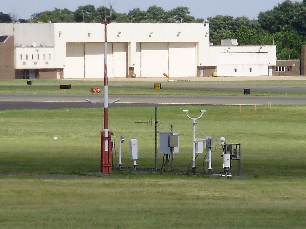
Some objects have to stand close to runways and taxiways: runway and taxiway lights, signs, markers and parts of navigation aids. Annex 14 accepts them only if they are frangible, designed to break, distort or give way on impact so that an aircraft that runs into them is damaged as little as possible.
- Anything that has to stand in the runway strip must be frangible, because the strip exists to protect an aircraft that runs off the runway.
- Every sign on the movement area is frangible, and those near a runway or taxiway are mounted low enough to clear propellers and the engine pods of jet aircraft.
- Taxiway edge markers, used where there are no edge lights, are frangible too.

Frangibility and the obstacle limitation surfaces work together. The surfaces keep solid obstacles away from the airspace an aircraft may need; frangibility makes the few objects that must stand inside it harmless. The markings, signs and lights concerned are described in aerodrome markings and signs and aerodrome lighting and visual aids.
Frequently asked questions
What is the difference between an aerodrome obstacle and an en-route obstacle?
An aerodrome obstacle is one that penetrates the obstacle identification surface out to a distance of 15 km from the aerodrome, and it is published in the aerodrome's AIP entry and obstacle charts. Beyond 15 km, objects are normally treated as en-route obstacles, obstacles to aircraft in flight, only if they are more than 150 m high. Lower but prominent objects near routes regularly used by helicopters may also be treated as obstacles.
What are obstacle limitation surfaces?
They are imaginary surfaces defined in ICAO Annex 14 around each runway: the approach, transitional, inner horizontal, conical, balked landing and take-off climb surfaces, among others. Together they mark the airspace that should be kept free of obstacles so that aircraft can approach, land, go around, take off and circle safely. An object that penetrates them is removed where possible, or else marked and lit, and operations may be restricted to allow for it.
What colour are obstacle lights?
Under ICAO Annex 14, low-intensity obstacle lights on fixed objects are steady red. Medium-intensity lights come in three types, flashing white (Type A), flashing red (Type B) and fixed red (Type C). High-intensity obstacle lights flash white, 40 to 60 times a minute, and mark objects more than 150 m high. Vehicles on the movement area show low-intensity flashing yellow lights.
Why are power lines marked with coloured balls?
Overhead wires and cables are among the most dangerous obstacles for low-flying aeroplanes and helicopters because they are almost invisible from the air, and the pylons that carry them can be far apart. Where they constitute obstacles, ICAO Annex 14 has them marked with coloured spheres fixed along the cables, which make their position and height visible from a distance.
What does frangible mean at an airport?
A frangible object is designed to break, distort or collapse on impact so that an aircraft striking it suffers as little damage as possible. Annex 14 requires anything that must stand in a runway strip, such as a light or a sign, to be frangible, and every sign on the movement area is frangible and mounted low enough to clear propellers and engine pods.
Test yourself on Obstacles and Obstacle Limitation Surfaces
The v1prep banks cover this topic in Air Law (010), with a worked explanation for every answer. EASA ATPL, PPL, IR and CPL, the FAA written tests and A320/B737 type ratings.
Start practising →Sources and further reading
- ICAO Annex 14, Aerodromes, Volume I, Aerodrome Design and Operations
- AIP France, GEN 1.7, Differences from ICAO Standards, Recommended Practices and Procedures (Annex 14, chapters 4 and 6)
- AIP France, ENR 1.5, Holding, Approach and Departure Procedures (departure gradients and obstacles)
- FAA Aeronautical Information Manual, Chapter 5 Section 2 (5-2-9, Instrument Departure Procedures and takeoff obstacles)
- FAA Aeronautical Chart Users' Guide
Library articles are written for study and exam preparation. They do not replace your aircraft's approved documentation, your operator's procedures or the regulations themselves.