A320 Hydraulic System
The A320 hydraulic system consists of three independent 3,000 psi systems, green, blue and yellow, each with its own reservoir and pumps. Flight controls are shared between them, and a power transfer unit links green and yellow without any exchange of fluid.
The Airbus A320 has three independent hydraulic systems, called green, blue and yellow. Each has its own reservoir and its own pumps, and all three run continuously at 3,000 psi. They move every flight control surface, the slats and flaps, the landing gear and brakes, nose wheel steering, the thrust reversers and the cargo doors, and the blue system also drives the emergency electrical generator.
The design aims to make any single failure a matter of lost redundancy rather than lost control. Users are spread so that each flight control axis is served by more than one system, and the power transfer unit (PTU) links green and yellow. The general principles of pumps, accumulators and transfer units are covered in hydraulic pumps and power sources; this article covers the A320 itself.
Three-system architecture
The A320 hydraulic systems (green, blue and yellow) never exchange fluid: each system's fluid stays in its own circuit. Normal pressure is 3,000 psi, or 2,500 psi when the blue system is powered by the ram air turbine.
| System | Normal source | Other sources |
|---|---|---|
| Green | Pump driven by engine 1 | PTU from yellow |
| Blue | Electric pump | Pump driven by the RAT |
| Yellow | Pump driven by engine 2 | Electric pump, hand pump, PTU from green |
Common features protect each system:
- An accumulator in each system covers transient demands and helps keep the pressure constant.
- Priority valves cut off heavy users when pressure falls, keeping it for the primary flight controls.
- A fire shutoff valve upstream of each engine-driven pump, green and yellow, closes when the crew push the ENG 1 or ENG 2 FIRE pushbutton, so that no fluid feeds an engine fire.
- The reservoirs are pressurised with high-pressure bleed air from engine 1, or from the crossbleed duct if that pressure is too low, to keep the pumps from cavitating.
- HP filters, return line filters and case drain filters clean the fluid. Maintenance inspects the case drain filters of the engine pumps and the blue electric pump for metal particles, a sign of pump wear.
Green hydraulic system
The green hydraulic system is pressurised by a pump driven by engine 1. Engine 1 thus has two hydraulic roles: it drives the green pump, and its bleed air normally pressurises all three reservoirs. Green supplies the landing gear and its doors, the normal brakes, the slats and flaps (each with a second system), the ground spoilers, the engine 1 thrust reverser and many flight control actuators. The autobrake needs green pressure to arm.
If engine 1 fails, the green pump stops, but with the PTU at AUTO the yellow system takes over through the PTU as soon as the pressure difference exceeds 500 psi. Green has no electric pump of its own.
Blue hydraulic system and RAT
The blue hydraulic system has no engine-driven pump. The blue electric pump, supplied from AC BUS 1, pressurises it. With its guarded BLUE ELEC PUMP pushbutton at AUTO and AC power available, the pump runs in flight, and on the ground when one engine is running or when the BLUE PUMP OVRD pushbutton on the maintenance panel is pressed. Blue supplies the slats (with green), flight control actuators and the emergency generator, the constant speed motor/generator (CSM/G). There is no PTU connection to blue, so losing AC BUS 1 alone depressurises it.
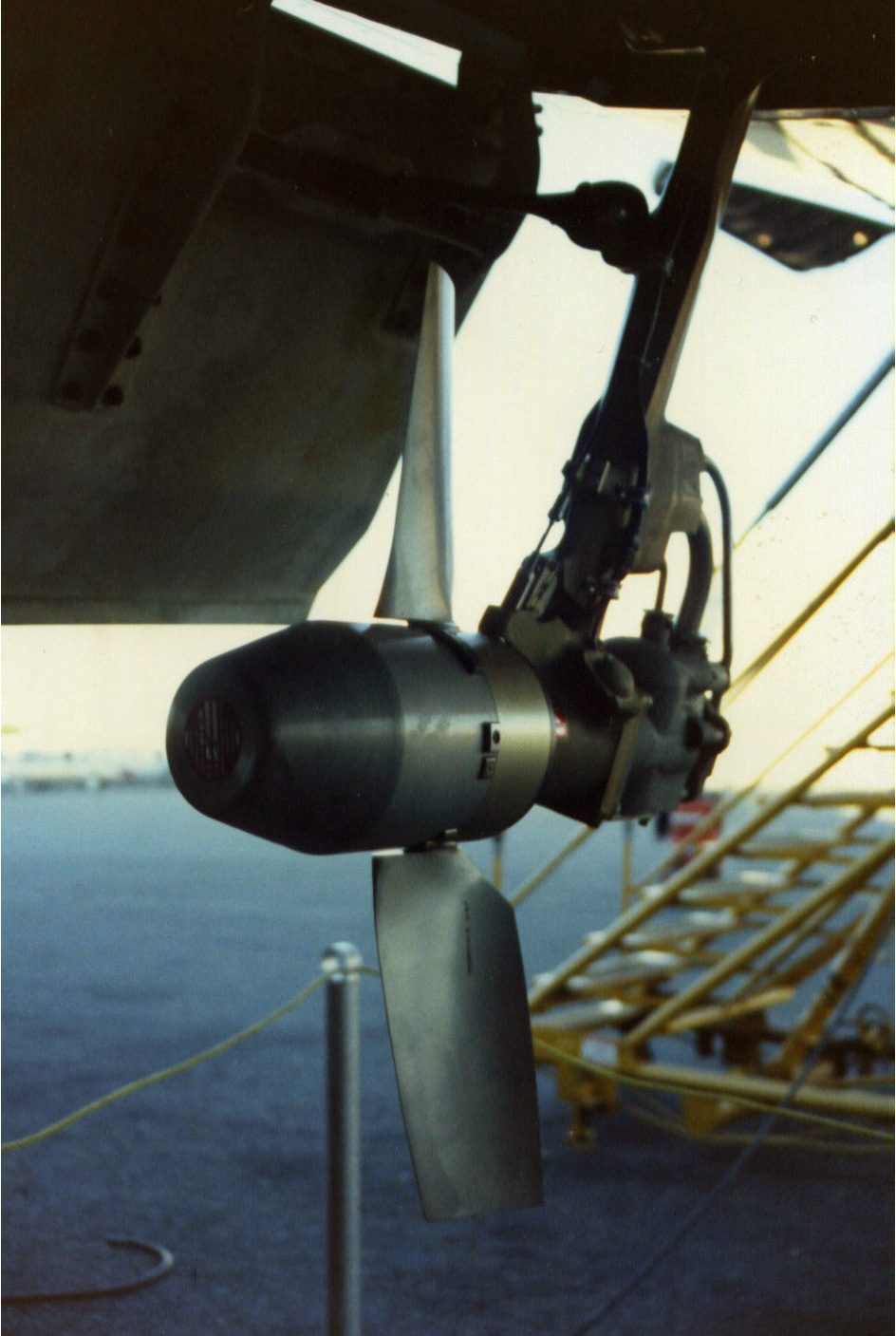
The ram air turbine (RAT) is a drop-out turbine coupled to a hydraulic pump on the blue system. It extends automatically when AC BUS 1 and AC BUS 2 are both lost with the aircraft above 100 kt, but not for the loss of one bus, and blue then works at 2,500 psi, also driving the emergency generator (see A320 electrical system). Two pushbuttons extend it manually:
- RAT manual deployment (RAT MAN ON), a guarded pushbutton on the HYD panel, extends the RAT at any time to pressurise blue.
- RAT manual extension (MAN ON), a guarded pushbutton on the EMER ELEC PWR panel, extends the RAT for emergency electrical generation; the emergency generator couples 3 s after the RAT supplies it.
Once extended, the RAT can be stowed only on the ground. The green RAT OUT memo shows it is not fully stowed, and it turns amber in flight phases 1 and 2, before take-off.
Yellow system and hand pump
The yellow hydraulic system is pressurised by a pump driven by engine 2. The yellow electric pump, supplied from AC BUS 2, allows yellow to be used on the ground with the engines stopped, and the yellow system hand pump pressurises it to operate the cargo doors when no electrical power is available. Yellow supplies the alternate brakes, the parking brake, nose wheel steering, the engine 2 thrust reverser, the cargo doors, the flaps (with green) and flight control actuators.
Engine 2 is normally started first because yellow pressurises the parking brake. The yellow electric pump starts by itself, even with its pushbutton off, when a cargo door manual selector lever is set to OPEN or CLOSE; the other yellow functions, the PTU included, are then inhibited except alternate braking and the engine 2 reverser. If electrical power is removed while the pump is ON, it stays off when power returns.
Power Transfer Unit
The power transfer unit (PTU) is a bidirectional unit between green and yellow: either system can pressurise the other, transferring power but not fluid. With the PTU pushbutton at AUTO, both its electrohydraulic valves are open and it runs automatically whenever the green-yellow pressure difference exceeds 500 psi. Selecting OFF closes both valves and stops the transfer. Its amber FAULT light covers the green or yellow reservoir: overheat, low air pressure or low fluid level.
The PTU covers an engine failure. With engine 2 failed, for example, green stays at 3,000 psi from engine 1, the difference with yellow exceeds 500 psi and the PTU powers yellow. On the ground it lets the yellow electric pump pressurise green with the engines stopped. It is inhibited during the first engine start and tested automatically during the second, when the green HYD PTU memo appears briefly and the PTU's barking sound is normal.
Leak measurement and maintenance panel
Each system has a leak measurement valve upstream of the primary flight controls. The valves are closed from the hydraulic maintenance panel with the LEAK MEASUREMENT VALVES pushbuttons: at OFF a valve closes and shuts off the hydraulic supply to the primary flight controls, so that the leakage of each circuit can be measured. Selecting ON reopens it.
The same panel carries the guarded BLUE PUMP OVRD pushbutton. At ON it runs the blue electric pump on the ground with the engines stopped, provided the BLUE ELEC PUMP pushbutton on the HYD panel is at AUTO. This is how blue is pressurised for ground checks.
HYD panel and ECAM HYD page
The overhead HYD panel carries the engine pump pushbuttons (ENG 1 PUMP and ENG 2 PUMP), the blue and yellow ELEC PUMP pushbuttons, the PTU pushbutton and the RAT MAN ON pushbutton. Selecting an ENG PUMP OFF depressurises the pump, which keeps turning with the engine, and stops hydraulic generation.
The FAULT lights share a logic. Every one covers a low reservoir level, a reservoir overheat and low reservoir air pressure; the pump pushbuttons add low pump pressure (inhibited on the ground with the engines stopped for the engine pumps and the blue pump), and the electric pumps add pump overheat. Each FAULT light goes out when OFF is selected, except during an overheat, when it stays on as long as the overheat lasts.
The ECAM hydraulic (HYD) page shows each system's pumps, pressure and reservoir:
| Indication | Meaning |
|---|---|
| System name and triangle | White and green above 1,450 psi; amber below |
| Pressure value | Green; amber below 1,450 psi |
| ENG PUMP symbol | Green in line: on, pressure normal; amber cross line: OFF; amber LO: on, pressure low |
| PUMP legend | Amber when N2 is below idle |
| PTU symbol | Green: AUTO, not transferring; amber: OFF; green arrows: direction of transfer |
| Reservoir quantity | Green; amber below the warning level |
| LO AIR PRESS, OVHT | Amber reservoir low air pressure or overheat, with ECAM caution |
| FIRE VALVE | Amber cross line: fully closed |
| RAT | White: stowed; green: not stowed; amber: stowing pressure applied or RAT pump not available |
The preliminary cockpit preparation uses this page to check the reservoir levels.
Single and dual hydraulic failures
A single system failure costs capability, not control. Each aileron has a green and a blue servojack, the left elevator a green and a blue one and the right elevator a yellow and a blue one, and three servojacks, one per system, move the rudder, so no axis is lost. The slats and flaps each depend on two systems, and with one inoperative they run at half speed.
A dual hydraulic failure leaves one system, and the consequences follow from the users listed above:
| Systems lost | Main consequences |
|---|---|
| Green and yellow | Pitch alternate law with reduced protection, roll direct, mechanical yaw; no stabiliser trim (its motors are green and yellow); no flaps; slats at half speed; braking on the brake accumulator only, without antiskid; no nose wheel steering; gear down by gravity |
| Green and blue | Ailerons in damping mode, roll by the remaining spoilers; no slats; flaps at half speed; alternate braking; gear down by gravity |
| Blue and yellow | No nose wheel steering or alternate braking; slats and flaps at half speed on green; normal brakes available |
The table gives only the main effects: in each case the ECAM procedure and the STATUS page list the inoperative systems (see A320 flight controls).
Exam tip: the PTU links only green and yellow, and needs a 500 psi difference to run. Blue has no PTU connection and no engine pump: its only sources are the electric pump on AC BUS 1 and the RAT.
Frequently asked questions
What are the three hydraulic systems on the A320?
The A320 has three continuously operating systems, green, blue and yellow, each with its own reservoir, at a normal pressure of 3,000 psi. Green is pressurised by a pump driven by engine 1, yellow by a pump driven by engine 2, with an electric pump and a hand pump as well, and blue by an electric pump, with a pump driven by the ram air turbine in an emergency.
How does the A320 power transfer unit work?
The PTU is a bidirectional unit between the green and yellow systems. It runs automatically when the pressure difference between them exceeds 500 psi, so either system can pressurise the other, transferring power but never fluid. It is inhibited during the first engine start and tested automatically during the second, and it lets the yellow electric pump pressurise the green system on the ground. It cannot help the blue system.
When does the blue electric pump run on the A320?
With its guarded pushbutton at AUTO and AC power available, the blue electric pump runs in flight, or on the ground when one engine is running or when the BLUE PUMP OVRD pushbutton on the maintenance panel is pressed. It is powered from AC BUS 1, so losing that bus alone stops it. The RAT does not extend for a single AC bus loss: it needs both AC BUS 1 and AC BUS 2 lost.
What happens after a green and yellow hydraulic failure on the A320?
Losing the green and yellow systems together leaves only blue. The flight controls revert to pitch alternate law with reduced protection, roll direct law and mechanical yaw. The stabiliser, moved by green and yellow motors, can no longer be trimmed, the flaps and nose wheel steering are lost, the gear is lowered by gravity and only the brake accumulator remains, without antiskid. The slats keep moving at half speed on blue.
Why is the A320's engine 2 usually started first?
Engine 2 drives the pump of the yellow hydraulic system, which also supplies the parking brake, so starting it first gives yellow pressure for the brakes before the second engine is started. The PTU is inhibited during this first start and tested automatically during the second, which is why its characteristic sound, and the green HYD PTU memo, are normal then.
Test yourself on A320 Hydraulic System
The v1prep banks cover this topic in the A320 type-rating bank, with a worked explanation for every answer. EASA ATPL, PPL, IR and CPL, the FAA written tests and A320/B737 type ratings.
Start practising →Sources and further reading
- EASA Type Certificate Data Sheet EASA.A.064, Airbus A318, A319, A320, A321
- EASA Easy Access Rules for Large Aeroplanes (CS-25), CS 25.1435 Hydraulic systems
- 14 CFR 25.1435, Hydraulic systems
- FAA Aviation Maintenance Technician Handbook, Airframe (FAA-H-8083-31B), Hydraulic and Pneumatic Power Systems
- EASA Easy Access Rules for Aircrew (Part-FCL), theoretical knowledge syllabus, 021 Airframe, Systems, Electrics, Power Plant
Library articles are written for study and exam preparation. They do not replace your aircraft's approved documentation, your operator's procedures or the regulations themselves.