A320 ECAM and Warning System
The Electronic Centralised Aircraft Monitor (ECAM) is the A320 system that shows engine parameters, system synoptics and crew alerts on the two central screens. Two flight warning computers generate its warnings, cautions, memos and aural alerts from data taken directly or through two system data acquisition concentrators.
The Electronic Centralised Aircraft Monitor (ECAM) is the half of the A320's electronic instrument system that looks after the aircraft rather than its flight path. On two screens in the centre of the panel it shows the engine parameters, the state of every system and, when something goes wrong, the alert and the procedure to apply. It decides what the crew sees according to the flight phase and the failure, so that most of the time it shows nothing but what the moment needs.
For the exam the ECAM is a matter of levels, colours and pushbuttons; for the line pilot it is the main tool for handling failures. The design principles behind it are in A320 flight deck design philosophy and the general theory in flight warning and alerting systems.
ECAM architecture: FWC and SDAC
Two identical flight warning computers (FWCs) generate the alert messages, memos, aural alerts and synthetic voice messages. They take the data for red warnings directly from the aircraft sensors and systems, and the data for amber cautions through two identical system data acquisition concentrators (SDACs). The SDACs acquire system data and send signals both to the FWCs and to the three display management computers (DMCs), which draw the system pages and engine parameters. The FWCs also produce the radio height and decision height callouts and drive the attention-getters in front of each pilot.
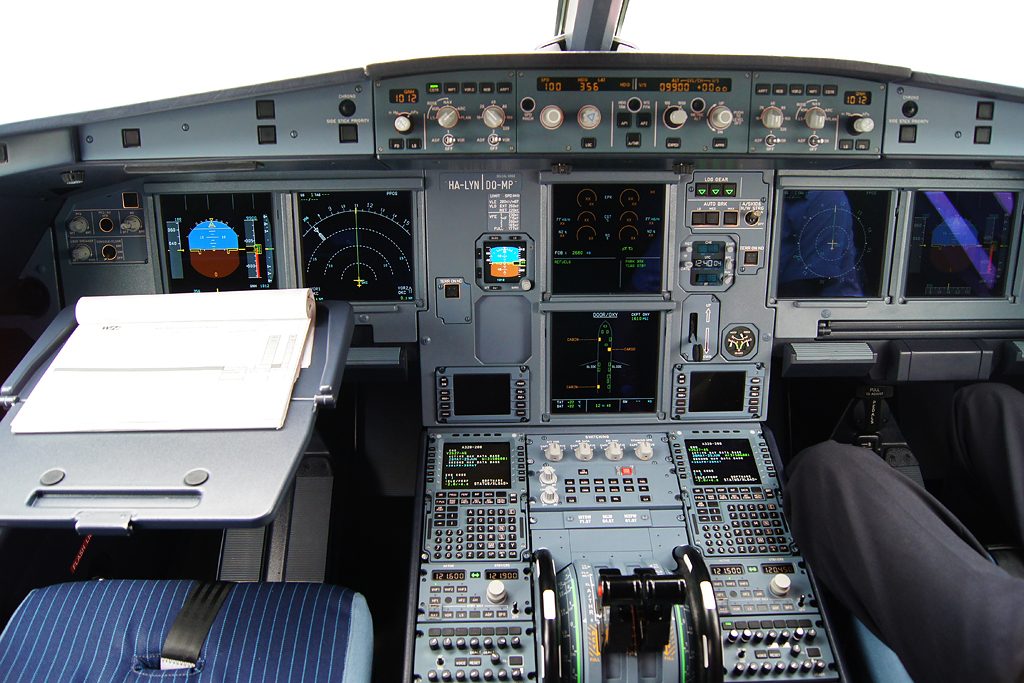
The ECAM uses the two central display units: the engine/warning display (E/WD) above and the system display (SD) below. With the pilots' primary flight and navigation displays they make up the six identical screens described in A320 EIS displays and EFIS controls. The loudspeakers give aural alerts and voice messages even when they are turned off.
Engine/Warning Display
The upper part of the E/WD shows the primary engine parameters, N1 (EPR on V2500 engines), EGT, N2 and fuel flow, with the thrust limit, fuel on board and slat and flap position. The lower part shows the FWC messages: warnings and cautions when a failure occurs, memos when there is none.
The lower part is split in two. On the left are primary or independent failures, with their procedures, or the memos. On the right are the systems affected, secondary failures, further memos and special lines such as AP OFF and LAND ASAP. A primary failure, which costs the aircraft the use of other systems, has a boxed title; a secondary failure, the loss of a system caused by a primary failure, has a star before the system name; an independent failure affects one system only. In the emergency electrical configuration secondary failures are inhibited. If the messages overflow, a green arrow points down and the pilot scrolls with the CLR pushbutton.
System Display and synoptic pages
The SD shows one of twelve system synoptic pages, ENGINE, BLEED, CAB PRESS, ELEC, HYD, FUEL, APU, COND, DOOR/OXY, WHEEL, F/CTL and CRUISE, or the STATUS page. Pages are called in four ECAM operating modes, sometimes called display modes: normal, the page that suits the flight phase; failure, the page of the failed system with the procedure on the E/WD; advisory, the page of a drifting parameter; and manual, any page except CRUISE chosen on the ECAM control panel. A failure or advisory page replaces a manually selected one.
Some automatic calls are worth knowing. The ENGINE page appears when a start begins or CRANK is selected and clears 10 seconds after the start, once the ENG MODE selector is back at NORM. The APU page appears when the APU MASTER SW is pressed and goes when the APU has been above 95 % for 10 seconds. In flight phase 2 the F/CTL page replaces the WHEEL page for 20 seconds when a sidestick moves more than 3° or a rudder pedal more than 22°.
Along the bottom of the SD the permanent data are shown in green: TAT and SAT, with the ISA deviation when standard pressure is set; the load factor, amber above 1.4 g or below 0.7 g for more than 2 seconds; UTC; and the gross weight from the first engine start. On any page, amber crosses replace a value that is not available, and amber dashes over the last digits show degraded accuracy.
ECAM valve symbols follow one convention: in line with the flow path means open, cross line means closed, green is normal, amber disagrees with the selection or is abnormal, and an amber symbol between the two positions is in transit. On the FUEL page an LP valve in line and amber, for example, is open with the ENG MASTER OFF.
The STATUS page summarises the aircraft's operational state after a failure: limitations and procedures in blue, approach procedures, information in green, cancelled cautions in white, inoperative systems in amber and maintenance status in white. If it is not empty, it appears by itself when the last alert is cleared and when CONF 1 is selected for the approach, and while it holds more than cancelled cautions or maintenance status an STS reminder is shown on the E/WD. Maintenance status is shown only on the ground, before engine start or after shutdown.
Alert levels and attention-getters
The ECAM alert levels grade failures by urgency. The FWC gives a level 3 warning priority over a level 2 caution, and a level 2 over a level 1:
| Level | Colour | Aural | Visual | Crew response |
|---|---|---|---|---|
| 3, warning | Red | Continuous repetitive chime, specific sound or synthetic voice | MASTER WARN flashing, message, system page | Immediate action |
| 2, caution | Amber | Single chime | MASTER CAUT steady, message, system page | Awareness, no immediate action |
| 1, caution | Amber | None | Message only, generally without procedure | Crew monitoring |
| Advisory | Green, pulsing | None | System page, parameter pulsing | Monitor the trend |
| Memo | Green, amber or magenta | None | Message | Reminder |
The attention-getters are a red MASTER WARN and an amber MASTER CAUT light under the glareshield in front of each pilot. A failure also lights the CLR pushbutton, and a local warning light may come on as well. A level 1 caution typically marks a loss of redundancy, such as an FCDC fault.

The main aural alerts are:
| Sound | Meaning |
|---|---|
| Continuous repetitive chime (CRC) | Red warning, until cancelled with MASTER WARN |
| Single chime (SC) | Amber caution, 0.5 second |
| Cavalry charge | Autopilot disconnection: 1.5 seconds with the takeover pushbutton, continuous after a failure |
| Triple click | Downgrade of landing capability, some mode reversions |
| Cricket and "STALL" | Stall warning, cannot be cancelled |
| C chord | Altitude alert |
| Buzzer | Cabin call, emergency cabin call, mechanic call |
Pressing MASTER WARN silences an aural warning, except for a few such as the overspeed, landing gear not down and stall alerts. The MASTER CAUT light goes out when pressed, when the condition ends, or with CLR or EMER CANC.
ECAM colour coding
The ECAM colour code gives each colour one meaning:
| Colour | Meaning |
|---|---|
| Red | Configuration or failure requiring immediate action |
| Amber | Configuration or failure to be aware of, no immediate action |
| Green | Item operating normally |
| White | Titles and remarks guiding the crew through procedures |
| Blue | Actions to be carried out, or limitations |
| Magenta | Particular messages, such as inhibition memos |
A procedure therefore reads as a red or amber alert title over blue action lines, with white remarks to guide the crew, and a blue line that remains is an action not yet done.
Memos and advisories
An ECAM memo recalls a function in temporary normal use. Memos are normally green, amber in abnormal situations and magenta for particular messages. GND SPLRS ARMED, IGNITION and HYD PTU are green; SPEED BRK turns amber when the speedbrakes should be retracted; RAT OUT is amber in flight phases 1 and 2; FUEL X FEED is amber in phases 3, 4 and 5.
The take-off memo and landing memo list the items to set before take-off and landing, each line blue until it is done, so the checks are "T.O memo, no blue" and "LDG memo, no blue". A successful T.O CONFIG test adds T.O CONFIG NORMAL to the take-off memo, and LDG GEAR DN in the landing memo confirms the gear downlocked. After a go-around that does not climb above 2,200 ft radio altitude, the landing memo reappears only below 800 ft on the next approach.
An ECAM advisory warns of a parameter drifting out of its normal range before it becomes a failure: the system page appears and the green value pulses, with no aural alert. Advisories are inhibited in some flight phases. With only one ECAM screen working, an advisory message appears on the E/WD and the related key on the ECAM control panel flashes.
Flight phases and inhibition
The FWCs divide each flight into ten FWC flight phases, independent of the FMGC's flight phases. Phases 1 and 2 cover the ground before take-off power is set, and the numbering then follows the flight through the take-off and landing to phase 10. Many alerts depend on them: ENG SHUT DOWN, for example, is triggered by an ENG MASTER set OFF in phases 3 to 8, or an ENG FIRE pushbutton pressed in phases 1, 2, 9 or 10.
Flight phase inhibition suppresses most warnings and cautions during critical parts of the take-off and landing, because most failures do not affect the aircraft's ability to continue them. The magenta T.O INHIBIT memo appears in phases 3, 4 and 5 and LDG INHIBIT in phases 7 and 8. Holding RCL for more than 3 seconds suppresses the inhibition until the next phase.
ECAM control panel
The ECAM control panel (ECP) is on the pedestal. Its main controls are:
- OFF/BRT knobs for each screen. Turning the upper screen off moves the E/WD to the lower screen.
- System page pushbuttons, which call a page and light up; a second push returns to the page of the flight phase or current warning. ALL shows every page in turn at 3-second intervals.
- CLR, lit while a warning, caution or status message is displayed. Once a procedure is complete it is pressed repeatedly until the memos and the flight phase page return and the light goes out.
- STS calls the STATUS page, which shows NORMAL for 3 seconds if empty.
- RCL recalls alerts cleared with CLR that are still active, or shows NORMAL for 3 seconds; held for more than 3 seconds it also recalls alerts cancelled with EMER CANC.
- EMER CANC. For a warning it stops the aural alert for as long as the failure lasts and puts out the MASTER WARN lights, leaving the message. For a caution it cancels everything for the rest of the flight. It is used only to suppress spurious cautions.
- T.O CONFIG, which tests the take-off configuration.
If the ECP fails, CLR, RCL, STS, EMER CANC and ALL still work, because they are wired directly to the FWCs and DMCs. When ECAM actions are under way, the pilot monitoring reads and applies them and the radio passes to the pilot flying. Memory items or OEB immediate actions come first, then any OEB, then the ECAM, then the QRH.
Take-off configuration test
The take-off configuration test (T.O CONFIG) simulates the application of take-off power. If the aircraft is not in take-off configuration a CONFIG warning appears; if it is, T.O CONFIG NORMAL appears in the take-off memo. The pilot monitoring performs it before take-off and checks the memo for blue lines.
Most configuration warnings come both from the test and from real take-off power: rudder trim, pitch trim, flaps, slats, speedbrakes, a sidestick fault, doors, brakes hot, a flap setting disagreeing with the MCDU, fuel and hydraulic low pressure, and an IDG disconnected. CONFIG PARK BRK ON and ENG THR LEVERS NOT SET come only with real take-off power. A generator fault triggers the test only if both generators are inoperative, but always at take-off power.
Warning: a T.O CONFIG NORMAL message does not prove that the parking brake is off. That warning, like the thrust lever one, needs real take-off power.
Frequently asked questions
What is the difference between the E/WD and the SD on the A320?
The engine/warning display, on the upper ECAM screen, shows the primary engine parameters, fuel on board and slat and flap position in its upper part, and the warning, caution and memo messages of the flight warning computers in its lower part. The system display, on the lower screen, shows one of twelve system synoptic pages or the STATUS page, with permanent data such as temperatures, time and gross weight along its bottom.
What are the ECAM warning levels on the A320?
Level 3 is a red warning for a configuration or failure needing immediate action, with a continuous repetitive chime or a specific sound and a flashing MASTER WARN light. Level 2 is an amber caution with a single chime and a steady MASTER CAUT light. Level 1 is an amber caution with no aural alert or master light, calling for crew monitoring. Advisories and memos sit below these levels.
What does the EMER CANC pushbutton do on the A320?
For a warning, EMER CANC stops the aural alert for as long as the failure lasts and puts out the MASTER WARN lights, but the ECAM message stays. For a caution, it cancels the chime, the MASTER CAUT lights and the message for the rest of the flight. Airbus restricts it to suppressing spurious cautions. Holding RCL for more than 3 seconds brings cancelled cautions back.
What is the difference between CLR and RCL on the ECAM control panel?
CLR, lit while a warning, caution or status message is shown, is pressed to move through the ECAM display once each procedure is complete, until the memos and the normal system page return. RCL recalls alerts that were cleared with CLR and are still active; held for more than 3 seconds, it also recalls those cancelled with EMER CANC and suppresses the flight phase inhibition until the next phase.
What does the T.O CONFIG test check on the A320?
Pressing T.O CONFIG simulates the application of take-off power. If the aircraft is not in take-off configuration, for example with flaps, slats, pitch trim, rudder trim or speedbrakes wrongly set, a configuration warning appears; otherwise T.O CONFIG NORMAL is shown in the take-off memo. The parking brake and thrust lever warnings are triggered only by real take-off power, not by the test.
What are T.O INHIBIT and LDG INHIBIT on the A320 ECAM?
They are magenta memos showing that most warnings and cautions are inhibited during critical phases of the take-off and landing, because most failures do not affect the aircraft's ability to continue them. T.O INHIBIT is shown in flight phases 3, 4 and 5 and LDG INHIBIT in phases 7 and 8. The flight warning computers define ten flight phases, independent of those of the flight management system.
Test yourself on A320 ECAM and Warning System
The v1prep banks cover this topic in the A320 type-rating bank, with a worked explanation for every answer. EASA ATPL, PPL, IR and CPL, the FAA written tests and A320/B737 type ratings.
Start practising →Sources and further reading
- EASA Easy Access Rules for Large Aeroplanes (CS-25), CS 25.1322 Flight crew alerting and CS 25.703 Take-off warning system
- 14 CFR 25.1322, Flightcrew alerting
- 14 CFR 25.703, Takeoff warning system
- EASA Type Certificate Data Sheet EASA.A.064, Airbus A318, A319, A320, A321
- JAA Joint Operational Evaluation Board Report A320 (2003), as published by EASA in the A320 OSD transition documents
- FAA Advisory Circular AC 25-11B, Electronic Flight Displays
- EASA, Explanatory Note to ED Decision 2018/001/R, Part-FCL theoretical knowledge learning objectives (022 Instrumentation)
Library articles are written for study and exam preparation. They do not replace your aircraft's approved documentation, your operator's procedures or the regulations themselves.