A320 Flight Deck Design Philosophy
The A320 flight deck design philosophy is the set of principles Airbus built into the cockpit and its procedures: a forward-facing two-pilot layout, system controls on the overhead panel following a lights-out logic, consistent colour codes for lights and screens, and displays that show only what the flight phase needs.
The flight deck of the Airbus A320 is built on a small number of principles that shape everything a crew sees and touches: two pilots facing forward, each able to monitor every instrument and system, the system controls gathered on the overhead panel, lights that stay out while all is well, consistent colour codes for lights and screens, and displays that show only what the moment needs. Airbus calls this its cockpit philosophy, and its procedures are written to match.
For a pilot starting an A320 type rating the philosophy explains why a dark overhead panel is the aim of every cockpit preparation, why a guarded pushbutton is pressed in flight only after a cross-check, why the standard operating procedures (SOPs) name some actions by seat, and why an Operations Engineering Bulletin can take precedence over the ECAM.
Airbus cockpit design philosophy
Airbus describes a safe and efficient flight as the product of three elements working together: the cockpit philosophy, the procedures and the pilots. The Airbus cockpit design philosophy rests on ten high-level design requirements. The first is that the flight crew is ultimately responsible for the safe operation of the aircraft. Another is that the crew can exercise full authority through intuitive actions while the risks of overstress and overcontrol are designed out, the root of the fly-by-wire protections. A third sets the priorities as safety, passenger comfort and efficiency, in that order. Another treats automation as an additional feature: the crew decide when to delegate and how much assistance they need.
The crew face forward, and both pilots can monitor the instruments and the systems. The arrangement aims to reduce workload, optimise task sharing and minimise head-down time.
- Glareshield: the short-term tactical controls of the auto flight system, used head-up and within easy reach of both pilots.
- Pedestal: engine and thrust controls (engine master levers, thrust levers), aircraft configuration (speed brake lever, flaps lever, rudder trim), navigation (MCDUs) and communication (radio management panels).
- Overhead panel: the system controls, concentrated there as pushbuttons set directly into a synoptic drawing of each system. The panels of systems linked to an engine are arranged vertically, so that normal and abnormal procedures run in a direct, intuitive order that limits errors.
Two further choices come from the same thinking. The thrust levers are not back-driven by the autothrust, so the crew judge energy from speed, speed trend and engine parameters rather than lever movement. The sidesticks are locked at neutral while the autopilot is engaged, so pilot and autopilot cannot give simultaneous inputs, and a firm push on the stick disconnects it instinctively.
The A320's eye position indicator is a red ball and a white light: the seat is correctly adjusted when the pilot's eyes are in line with them (see flight deck layout and master warnings).
Dark cockpit and need-to-see
The general operational rule of the overhead panel is the lights-out philosophy, which gives the dark cockpit its name: with the aircraft in a normal configuration and its systems ready and fit to fly, the pushbuttons are blank. Only green lights may stay on permanently, and blue lights only intermittently. Any other light means something: a failure, an abnormal selection, or a test or maintenance indication. Cockpit preparation is largely the work of reaching a dark panel.
The same economy governs alerts. An alert is required when a system fails, the aircraft leaves the normal flight envelope, an unexpected safety event occurs (a TCAS or TAWS alert), a message arrives from the cabin or ATC, or a system changes its mode by itself, such as an autopilot disconnection. A failure is then signalled at several levels at once: the MASTER WARN or MASTER CAUT light with its aural alert, the alert title on the engine/warning display (EWD), the affected system's page on the system display (SD), and an amber or red light in that system's pushbutton on the overhead panel, which leads the hand to the corrective control.
The need-to-see concept applies the same restraint to the six display units, which could otherwise overload the crew. Its principles are:
- the right information for the flight phase;
- uncluttered displays showing what needs to be shown;
- redundant or consolidated data for safety-related parameters;
- predictive information on essential parameters, such as the speed trend.
The ECAM shows the idea at work: a system page appears by itself when a failure needs it, and during take-off and landing most alerts are inhibited, the magenta T.O INHIBIT memo being displayed in flight phases 3, 4 and 5 and LDG INHIBIT in phases 7 and 8 (see A320 ECAM and warning system).
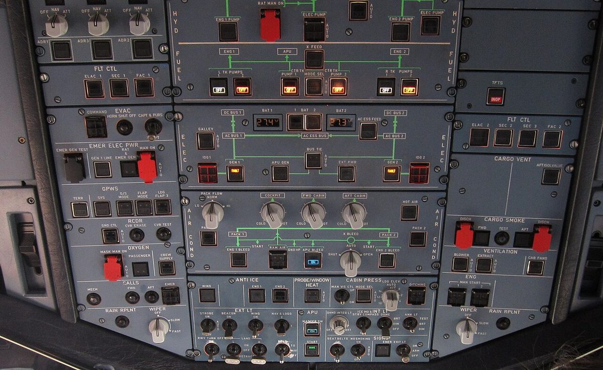
Pushbutton types and lights
Wherever possible, a pushbutton used for a corrective action carries its own status and failure lights, so that the control and its indication are one object. A pushbutton switch (pb-sw) latches in one of two positions, and Airbus standardises what they mean:
| Position | Typical functions |
|---|---|
| Pressed in | ON, AUTO, OVRD, OPEN |
| Released out | OFF, MAN, ALTN, SHUT |
In its normal position a pushbutton is dark. A released-out pushbutton therefore usually shows a white legend such as OFF or ALTN, white being the colour of an abnormal pushbutton position. A fuel pump pushbutton, for example, shows a white OFF when the pump is selected off and an amber FAULT when the pump delivers low pressure. Two dots on part of a lens mean that part of the pushbutton is not used. A momentary action pushbutton does not remain pressed in: it springs back when released.
The amber pushbutton FAULT light usually comes with an ECAM caution, and because corrective controls carry their own failure lights, it marks the control the procedure is likely to use. Its logic has details worth knowing: the hydraulic pump FAULT lights go out when OFF is selected, except during an overheat, and the ELAC FAULT light comes on during the computer's eight-second power-up test.
A guarded pushbutton sits under a hinged cover, often red, that must be lifted first. Guards protect controls whose inadvertent use would be serious or irreversible, such as the IDG disconnect, the RAT manual extension and the evacuation COMMAND pushbutton. In flight, the PF and PM must cross-check before any action on an engine master lever, an IR mode selector, any guarded control or a cockpit circuit breaker. The PM points to the control, the PF confirms it, and the PM operates it, announcing system, control and action, for example "AIR, X BLEED, CLOSE".
The lamps are proved with the Annunciator Light Test (ANN LT). With the ANN LT switch at TEST, every flight deck annunciator lights and the figure 8 appears on all the liquid crystal displays of the flight control unit (FCU); the display units must not be reconfigured meanwhile. At DIM or BRT the switch sets the brightness of all annunciators together.
Exam tip: on a pushbutton, white is not a failure. A white light marks an abnormal pushbutton position or a test result; blue marks a system used temporarily and working normally; amber and red are failures.
Cockpit colour coding
Cockpit colour coding uses the same colours on lights and screens. Red, amber and green mean much the same on both, but blue and white do not:
| Colour | Pushbuttons and annunciators | ECAM and displays |
|---|---|---|
| Red | Warning: failure requiring immediate action | Configuration or failure requiring immediate action |
| Amber | Caution: failure to be aware of, no immediate action | Configuration or failure to be aware of, no immediate action |
| Green | Normal system operation | Item operating normally |
| Blue | Normal operation of a system used temporarily | Actions to be carried out, or limitations |
| White | Abnormal pushbutton position; test or maintenance information | Titles and remarks guiding the crew through procedures |
| Magenta | Not used | Particular messages, such as inhibition memos |
The alert hierarchy uses the same code. A level 3 warning is red, with a continuous repetitive chime or a specific sound and a flashing MASTER WARN light. A level 2 caution is amber, with a single chime and a steady MASTER CAUT light. A level 1 caution is amber, has no aural alert and calls for crew monitoring. Memos, normally green, remind the crew of functions in temporary use.

Crew roles: CM1 and CM2
Airbus procedures use two pairs of labels. Crew Member 1 (CM1) is the pilot in the left seat, normally the captain, and Crew Member 2 (CM2) the pilot in the right seat. Some SOP actions belong to a seat rather than a role. At power-up and aircraft acceptance, CM2 checks the batteries, the engine master levers OFF and the ENG MODE selector at NORM, and CM1 presses the RCL key for 3 s to recall the warnings cleared or cancelled during the last flight. When the aircraft is secured, CM1 checks the parking brake on and sets the IR mode selectors OFF, while CM2 switches off the APU bleed, the APU and the batteries.
Flight duties go by role. The pilot flying (PF) flies and navigates; the pilot monitoring (PM) monitors the flight path, the navigation and the systems, and communicates. In abnormal operations the PF also takes the radio once the ECAM or QRH actions have been started, because the PM's attention goes to understanding and applying the procedure. The PM reads and does the actions aloud and obtains the PF's confirmation before clearing any ECAM alert. The thrust levers belong to the PF. With the autopilot on, the PF makes the FCU entries; with it off, the PM makes them at the PF's request. A pilot taking control announces "I have control" and presses and holds the sidestick pushbutton.
All of this sits within Airbus's four golden rules: fly, navigate, communicate; use the appropriate level of automation; understand the FMA; and take action if things do not go as expected (see standard operating procedures and checklists).
Cockpit preparation and power-up tests
The SOPs consist of inspections, preparations and normal procedures, and assume that every system works and that the automatic functions are used normally. Within each procedure the items follow a standardised scan of the cockpit panels, unless that order conflicts with the priority of actions, so every crew works through the panels in the same sequence.
The day starts with the safety exterior inspection: wheel chocks in place, or the parking brake set with sufficient accumulator pressure, and the landing gear doors checked before any hydraulic system is pressurised. If the aircraft has not been electrically supplied for 6 h or more, CM2 checks with the BAT pushbuttons OFF that each battery reads above 25.5 V, which means a charge above 50 %; otherwise a charging cycle of about 20 minutes is needed.
Applying power starts automatic power-up tests, and the crew should expect their signs. Each ELAC runs an eight-second test, with its FAULT light and an ECAM caution, whenever power is applied or after an electrical transient longer than 25 ms. The APU's electronic control box tests itself when the APU MASTER SW is pressed, and both flight directors engage by themselves at power-up on the ground.
The preliminary cockpit preparation follows. The HYD, ENG and DOOR pages of the system display show the hydraulic reservoir levels, the engine oil quantities and the oxygen pressure, and the crew review the OEBs that apply to the aircraft. The exterior walkaround and the cockpit preparation proper come next; both pilots cross-check the take-off data, and before take-off the T.O CONFIG test confirms the take-off configuration.
OEB and Operations Library
An Operations Engineering Bulletin (OEB) is an operational procedure issued by Airbus for the aircraft to which it applies. It can supersede an ECAM procedure, a STATUS message or both. Crews give particular attention to red OEBs, especially those to be applied before the ECAM procedure, and some OEBs contain OEB immediate actions, applied from memory like memory items. In an abnormal or emergency situation the order is therefore: memory items or OEB immediate actions, then the OEB, then the ECAM, then the QRH. Where the OEB reminder function is fitted, the ECAM shows in real time that an alert is affected by an OEB and displays a message telling the crew to refer to the QRH; the flag may cover an ECAM procedure alone, a procedure and its status messages, or a status message alone.
The documents themselves are increasingly electronic. The SOPs assume that both pilots use an electronic flight bag (EFB), and Airbus recommends two to reduce the risk of erroneous inputs. In the FlySmart with Airbus suite, the Operations Library (OLB) application gives on-board access to Airbus's FCOM, MEL, AFM, CDL and FCTM and to the airline's own manuals. MEL and CDL items selected there pass automatically to the take-off and landing performance applications, and the electronic QRH (eQRH) holds the normal checklists, some abnormal procedures and the OEBs.
The FCOM describes a basic configuration that may differ from an individual aircraft; for emergency equipment, the placards on board are authoritative. See operations manual and flight crew documentation.
Frequently asked questions
What is the dark cockpit philosophy on the Airbus A320?
Dark cockpit, or the lights-out principle, means that when the aircraft is in a normal configuration with its systems fit to fly, the overhead pushbuttons show no lights. Only green lights may stay on permanently, and blue lights only for a time. Any other light signals something the crew must understand: an amber or red failure, or a white abnormal pushbutton position. Cockpit preparation aims at a dark panel.
What do the colours of the A320 pushbutton lights mean?
Red means a failure that requires immediate action. Amber means a failure the crew should be aware of but that does not call for immediate action. Green shows normal operation of a system, and blue the normal operation of a system used only temporarily. White shows an abnormal pushbutton position or a test or maintenance indication. No light at all means the system is normal and fit to fly.
What is the difference between CM1, CM2, PF and PM on the A320?
CM1 and CM2 identify the seat: CM1 is the left-seat pilot, normally the captain, and CM2 the right-seat pilot, and some SOP actions are allocated by seat. PF and PM identify the role: the pilot flying flies and navigates, the pilot monitoring monitors and communicates. Either seat can be the pilot flying, and control changes hands with the callouts I have control and you have control.
What is an OEB on the Airbus A320?
An Operations Engineering Bulletin is an operational procedure issued by Airbus for the aircraft to which it applies. It can supersede an ECAM procedure, a STATUS message or both. Crews review the applicable OEBs during the preliminary cockpit preparation, with particular attention to red OEBs that must be applied before the ECAM procedure. Some contain immediate actions which, like memory items, are applied from memory.
How are the annunciator lights tested on the A320?
The crew set the ANN LT switch on the overhead panel to TEST. All flight deck annunciator lights come on and the figure 8 appears on every liquid crystal display of the flight control unit, so a failed lamp or segment shows up. The display units must not be reconfigured and the display management computers must not be switched during the test. The DIM and BRT positions set the brightness of all annunciators together.
Test yourself on A320 Flight Deck Design Philosophy
The v1prep banks cover this topic in the A320 type-rating bank, with a worked explanation for every answer. EASA ATPL, PPL, IR and CPL, the FAA written tests and A320/B737 type ratings.
Start practising →Sources and further reading
- JAA Joint Operational Evaluation Board Report A320 (2003), as published by EASA in the A320 OSD transition documents
- EASA Type Certificate Data Sheet EASA.A.064, Airbus A318, A319, A320, A321
- EASA Easy Access Rules for Large Aeroplanes (CS-25), CS 25.1302 Installed systems and equipment for use by the flight crew, CS 25.1322 Flight crew alerting
- 14 CFR 25.1322, Flightcrew alerting
- EASA Easy Access Rules for Air Operations (Regulation (EU) No 965/2012), ORO.MLR manuals, logs and records
- ICAO Doc 9683, Human Factors Training Manual
Library articles are written for study and exam preparation. They do not replace your aircraft's approved documentation, your operator's procedures or the regulations themselves.