A320 Flight Controls: Architecture and Computers
The A320 flight control system is a fly-by-wire system in which seven computers, two ELACs, three SECs and two FACs, turn sidestick and autopilot orders into commands for hydraulically powered surfaces, with a mechanical backup through the stabiliser trim wheels and the rudder pedals.
The A320 brought full digital fly-by-wire to airline service. Every control surface is commanded electrically and moved hydraulically; the pilots fly with sidesticks, and computers turn their inputs, or the autopilot's, into surface orders. Only the trimmable horizontal stabiliser and the rudder keep a mechanical link to the cockpit, as a last-resort backup.
This article describes the hardware: the computers, the surfaces they drive, the actuators and the sidesticks. How the computers shape the aircraft's response, and the protections they provide, are covered in A320 flight controls: laws and protections; the general principles are in fly-by-wire.
Fly-by-wire overview
All the A320's flight control surfaces are electrically controlled and hydraulically actuated. The pilots use the sidesticks to fly in pitch and roll; yaw is controlled indirectly, through turn co-ordination.
| Axis | Surfaces | Control |
|---|---|---|
| Pitch | Two elevators | Electrical |
| Pitch | Trimmable horizontal stabiliser (THS) | Electrical in normal and alternate control; mechanical through the trim wheels |
| Roll | One aileron and four spoilers per wing | Electrical |
| Yaw | Rudder | Mechanical from the pedals; electrical for yaw damping, turn co-ordination and trim |
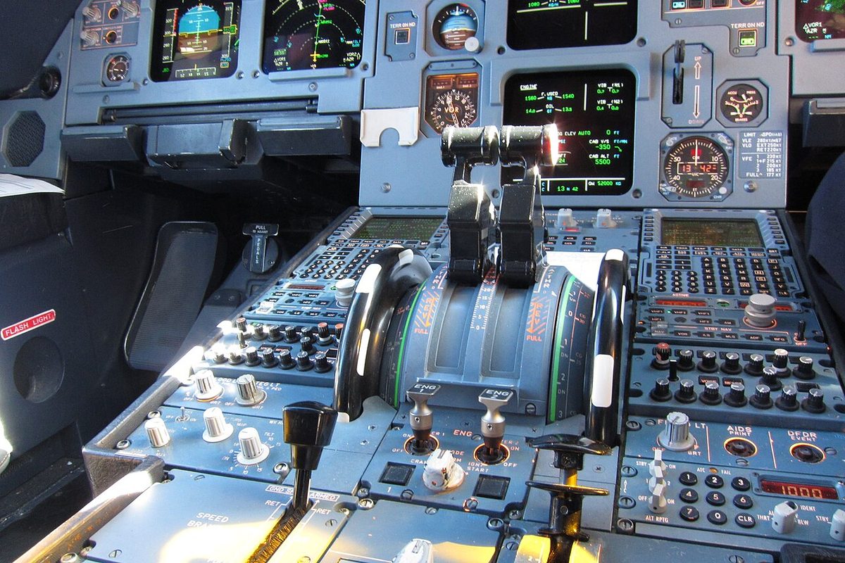
The cockpit controls are two sidesticks, two pairs of rigidly interconnected rudder pedals, mechanically interconnected pitch trim wheels on each side of the pedestal, a speed brake lever and a rudder trim selector. There is no aileron trim: the control laws take care of it.
The mechanical backup is the final layer. Pitch is then controlled by trimming the THS with the wheels, and the aircraft is controlled laterally with the rudder pedals; the PFDs show MAN PITCH TRIM ONLY in red. It exists to manage a temporary total loss of electrical power, a temporary loss of five fly-by-wire computers, the loss of both elevators or the total loss of the ailerons and spoilers.
ELAC, SEC and FAC computers
Seven computers process the pilots' and autopilot inputs:
- The two elevator aileron computers (ELAC) handle normal elevator, stabiliser and aileron control. Their functions are normal pitch and roll, alternate pitch, direct pitch and roll, the abnormal attitude law, aileron droop, acquisition of autopilot orders and the load alleviation function (LAF), in its normal and alternate forms.
- The three spoiler elevator computers (SEC) control the spoilers for roll, the speedbrakes and the ground spoilers, and provide direct roll and an alternate load alleviation function. SEC 1 and SEC 2 also provide standby elevator and stabiliser control, in alternate and direct pitch.
- The two flight augmentation computers (FAC) control the rudder electrically: normal yaw (yaw damping and turn co-ordination), alternate yaw, rudder trim and rudder travel limiting. They also compute the characteristic speeds on the PFD speed scale, alpha floor, the low-energy warning and windshear detection.
ELACs and SECs come from different manufacturers and run different software, so a single design error is unlikely to disable both types at once. Each computer also has a command and a monitor channel, and disconnects itself if they disagree. In addition, two flight control data concentrators (FCDC) acquire data from the ELACs and SECs and send it to the displays and the centralised fault display system.
Each computer has a pushbutton on the overhead FLT CTL panels; switching an ELAC OFF and back ON resets it. The ELAC FAULT light comes on amber, with an ECAM caution, for a detected failure and during the eight-second power-up test.
Pitch control and THS trim
Two elevators and the trimmable horizontal stabiliser (THS) control pitch. The elevators deflect up to 30° nose up and 17° nose down; the THS moves between 13.5° nose up and 4° nose down.
Normally ELAC 2 controls pitch: the green and yellow servojacks drive the left and right elevators, and electric motor No. 1 drives the THS. If ELAC 2, or its hydraulic systems or jacks, fail, ELAC 1 takes over with the blue servojacks and THS motor No. 2. With both ELACs lost, pitch passes to SEC 1 or SEC 2 and to THS motor No. 2 or No. 3. If one elevator fails, the travel of the other is limited to avoid asymmetric loads on the tailplane and rear fuselage.
The THS is moved by a screwjack driven by two hydraulic motors. These are controlled by one of three electric motors or by the pitch trim wheel, which works whenever the green or yellow system is pressurised and has priority over electrical control. Moving the wheel disconnects the autopilot but not the ELACs. After engine start the crew set the THS for the take-off centre of gravity with the wheels; after landing, once the pitch attitude has been below 2.5° for more than 5 s, the THS returns to zero by itself. In flight in normal law, automatic pitch trim keeps the THS trimmed without crew action, and the wheels turn by themselves; in direct law there is no automatic trim.
Roll control: ailerons and spoilers
Each wing has one aileron and four roll spoilers, numbered 2 to 5; spoiler 1 is a ground spoiler only. The ailerons deflect up to 25° and the spoilers up to 35° for roll. With the flaps extended, aileron droop lowers both ailerons by 5° to add lift.
ELAC 1 normally controls the ailerons, and ELAC 2 takes over if it fails. Each aileron has two servojacks, green and blue, only one active at a time. If both ELACs fail, or blue and green pressure are both low, the ailerons go to damping mode and the spoilers alone control roll.
Each spoiler has one servojack, supplied by green, yellow or blue. For roll, SEC 3 controls the No. 2 spoilers, SEC 1 the No. 3 and No. 4, and SEC 2 the No. 5. A spoiler whose SEC fails, or which loses electrical control, retracts. One that loses hydraulic pressure keeps its deflection, or less if the airflow pushes it down. When a spoiler fails on one wing, the symmetrical one is inhibited.
Yaw control and rudder limiting
Three independent servojacks, one per hydraulic system, move the rudder in parallel. In automatic operation a green servo actuator drives them, with a yellow one synchronised to take over. The ELACs compute the yaw damping and turn co-ordination orders and send them to the FACs; the pedals receive no feedback from these functions.
The rudder travel limit, a FAC function, reduces the maximum rudder deflection as speed increases to avoid excessive structural loads. Full pedal travel always remains, but except at low speed maximum rudder deflection is reached before full pedal. If the function fails, the limit freezes at its last value, and full authority returns when the slats extend. The F/CTL page shows the travel limiter unit (TLU) amber when both limiters have failed.
The rudder trim is driven by motor No. 1 under FAC 1, with FAC 2 and motor No. 2 synchronised as a backup. The RUD TRIM selector moves the neutral point at 1° per second, and the reset pushbutton returns it to zero at 1.5° per second. With the autopilot engaged, the FMGC computes rudder trim and the crew's controls are inactive.
The flight envelope protections are not designed as structural limit protections against inappropriate rudder inputs, such as opposite rudder pedal inputs. The warning system can call STOP RUDDER INPUT, a synthetic voice repeated at least twice, when it detects inappropriate rudder pedal inputs in cruise at high speed (see yaw dampers and rudder limiting).
Speedbrakes and ground spoilers
The speedbrake lever on the pedestal extends spoilers 2, 3 and 4. In manual flight spoilers 3 and 4 reach 40° and spoiler 2 reaches 20°, reduced to 25° and 12.5° in CONF 0 when the weight exceeds the maximum landing weight by more than 2 t. With the autopilot engaged the maximum is 25° and 12.5°, obtained at the half position, where the lever has a hardpoint. When a surface receives both a roll and a speedbrake order, roll has priority. Above 315 kt or M 0.75 with the autopilot engaged, retraction from full to clean takes about 25 s.
Speedbrake inhibition applies when SEC 1 and SEC 3 are both faulty, an elevator has a fault, angle of attack protection or alpha floor is active, the flaps are at CONF FULL, or a thrust lever is above MCT. Extended speedbrakes then retract and stay retracted until the condition has gone and the lever has been reset, and can be extended again 10 s later. An amber SPEED BRK memo shows when they should be retracted.
The ground spoiler function uses all five spoilers and the ailerons. Ground spoilers are armed by pulling the speedbrake lever up. In a rejected take-off above 72 kt wheel speed they extend when both thrust levers reach idle, or, if not armed, when reverse is selected on one engine. On landing they extend fully with both main gears on the ground and both levers at idle or reverse selected. Phased lift dumping (PLD) extends them partly when only one main gear is on the ground. When the ground spoilers are fully extended, aileron anti-droop fully deflects both ailerons as part of the ground spoiler function, provided one aileron servojack is available on each side, the flaps are not clean, the pitch attitude is below 2.5° and the aircraft is flown manually in normal law. The spoilers retract when disarmed, or in a touch-and-go when a thrust lever passes 20°.

Sidesticks and priority logic
The sidesticks are spring-loaded to neutral, not linked to each other, give no feedback from the surfaces and are locked at neutral while the autopilot is engaged. A force above 5 daN in pitch or 3.5 daN in roll disconnects the autopilot, although this is not the recommended method. Each sidestick has a radio push-to-talk switch and a takeover pushbutton.
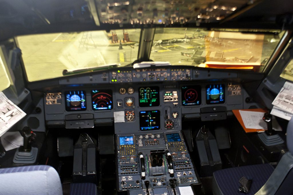
If both pilots move their sticks, the orders are added algebraically and limited to one full deflection; the green CAPT and F/O lights on the glareshield flash and a dual input voice message sounds. Sidestick priority is taken with the sidestick takeover pushbutton, also called the sidestick priority pushbutton. Pressing and holding it deactivates the other stick, and the last pilot to press has priority. A PRIORITY LEFT or PRIORITY RIGHT voice sounds, and a red arrow lights in front of the pilot losing authority. Holding the pushbutton for 40 s latches the priority until either pilot presses a pushbutton again. A sidestick deactivated on the ground triggers CONFIG L(R) SIDESTICK FAULT at take-off power or during the T.O CONFIG test.
On the ground after the first engine start, a white sidestick position indication appears on both PFDs; it disappears when the aircraft becomes airborne.
Actuator modes and FCDC monitoring
Each elevator has two servojacks, and each jack has three control modes, the servojack control modes:
| Mode | What the jack does |
|---|---|
| Active | Position electrically controlled |
| Damping | Follows the surface movement |
| Centring (Airbus: centering) | Held hydraulically at neutral |
Normally one elevator jack is active and the other damping, although some manoeuvres make both active. If the active jack fails, the other becomes active. With no electrical control both jacks centre; with no hydraulic pressure both go to damping. Aileron jacks have only active and damping modes.
The FCDC data feed the ECAM F/CTL page. Each ELAC and SEC number is green in a grey box, turning amber if the computer fails or is switched OFF. The G and B labels of the aileron and elevator actuators turn amber on low green or blue pressure. An aileron index turns amber when neither of its servojacks is available, an elevator index when both its actuators are lost, and the rudder symbol only when all three systems are low.
Frequently asked questions
What do the ELAC, SEC and FAC do on the A320?
The two ELACs (elevator aileron computers) provide normal pitch and roll control through the elevators, stabiliser and ailerons. The three SECs (spoiler elevator computers) control the spoilers, speedbrakes and ground spoilers, and SEC 1 and SEC 2 provide standby elevator and stabiliser control. The two FACs (flight augmentation computers) control the rudder electrically: yaw damping, turn co-ordination, rudder trim and rudder travel limiting.
How does sidestick priority work on the A320?
If both pilots move their sidesticks, the inputs are added algebraically, limited to the equivalent of one full deflection, green lights flash and a DUAL INPUT voice sounds. Pressing and holding the takeover pushbutton deactivates the other sidestick; the last pilot to press gets priority, a PRIORITY LEFT or RIGHT voice sounds and a red arrow lights in front of the pilot who lost authority. Holding it for 40 seconds latches the priority.
Which spoilers are the speedbrakes on the A320?
Spoilers 2, 3 and 4 on each wing act as speedbrakes. In manual flight spoilers 3 and 4 reach 40 degrees and spoiler 2 reaches 20 degrees; with the autopilot engaged the maximum is 25 and 12.5 degrees, obtained with the lever at the half position. Spoilers 2 to 5 assist the ailerons in roll, spoiler 1 is a ground spoiler only, and all five dump lift on the ground.
When are the A320 speedbrakes inhibited?
Speedbrake extension is inhibited when SEC 1 and SEC 3 are both faulty, when an elevator has a fault, when angle of attack protection or alpha floor is active, with the flaps at CONF FULL, and with a thrust lever above MCT. Extended speedbrakes then retract automatically and stay retracted until the condition has gone and the crew have reset the lever; they can be extended again 10 seconds later.
Can the A320 be flown without its flight control computers?
Yes, for a limited time. The mechanical backup lets the pilot control pitch by moving the trimmable horizontal stabiliser with the pitch trim wheels, and lateral attitude with the rudder pedals, both mechanically linked. It is designed for rare cases such as a temporary total loss of electrical power or of five flight control computers, and the PFDs then show MAN PITCH TRIM ONLY in red.
Test yourself on A320 Flight Controls: Architecture and Computers
The v1prep banks cover this topic in the A320 type-rating bank, with a worked explanation for every answer. EASA ATPL, PPL, IR and CPL, the FAA written tests and A320/B737 type ratings.
Start practising →Sources and further reading
- Airbus, Safety innovation
- Traverse, P. et al., Airbus Fly-by-Wire, A Total Approach to Dependability (ICAS 2006)
- EASA TCDS EASA.A.064, Annex I, Special Conditions and Equivalent Safety Findings
- EASA Easy Access Rules for Large Aeroplanes (CS-25), CS 25.671 Control systems, general, and CS 25.672 Stability augmentation and automatic and power-operated systems
- 14 CFR 25.671, Control systems, general
Library articles are written for study and exam preparation. They do not replace your aircraft's approved documentation, your operator's procedures or the regulations themselves.