Flight Deck Layout and Master Warnings
Flight deck layout is the arrangement of seats, panels, controls and displays around the pilots' eye reference position: flight instruments in front of each pilot, shared controls on the glareshield and pedestal, and system controls overhead, with master warning and caution lights placed where both pilots will see them at once.
The flight deck of a transport aeroplane is laid out so that two pilots, facing forward, can fly, navigate, communicate and manage the systems while each can see and check what the other is doing. Its geometry starts from one point, the eye reference position, and its controls are grouped by how often and how urgently they are used: flight instruments straight ahead, tactical autoflight controls on the glareshield, engine, configuration and radio controls on the centre pedestal, and the aircraft systems on the overhead panel.
Superimposed on the layout is the alerting system. When something goes wrong, the crew must notice it at once, whichever panel they happen to be looking at. Master warning and master caution lights, placed in each pilot's field of view, draw the eye to a failure, and lamp tests make sure those lights work when they are needed. Certification sets the frame: CS-25 and 14 CFR Part 25 cover the pilot compartment, its view and its controls in 25.771 to 25.781 and crew alerting in 25.1322.
Flight deck layout
Airbus states the aim of the A320's forward-facing layout plainly: to reduce crew workload, optimise task sharing and minimise head-down time, with the controls arranged so that both crew members can monitor the instruments and systems. Most airliners share the same zones:
| Zone | Contents (A320 examples) |
|---|---|
| Main instrument panel | Each pilot's primary flight and navigation displays; in the centre the engine and warning display above the system display, beside the standby instruments |
| Glareshield | Flight control unit (autoflight panel between two EFIS control panels), master warning and master caution lights, sidestick priority lights |
| Centre pedestal | Thrust levers and engine master levers, speed brake and flap levers, rudder trim, MCDUs, radio management panels, ECAM control panel, pitch trim handwheels |
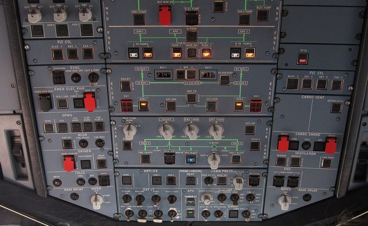
| Overhead panel | System controls: electrical, hydraulic, fuel, air conditioning, pressurisation, anti-ice, oxygen, cargo smoke, lights |
| Side consoles | Sidesticks, lit by each pilot's console lighting |
The glareshield carries the short-term tactical controls of the autoflight system, so that either pilot can use them head-up. The pedestal, between the seats, holds controls both pilots must reach: on the A320 the engine and thrust controls, the configuration controls, the MCDUs and the radio panels, as well as the gravity gear extension crank and the cockpit door DOOR UNLOCK pushbutton. Boeing's equivalents are the mode control panel and system annunciator panels on the glareshield and the control stand with its thrust levers, speed brake lever and stabiliser trim wheels.
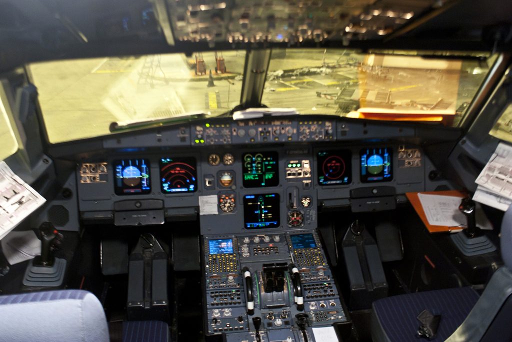
Seats complete the layout. The A320's two pilot seats, mounted on columns, adjust electrically or mechanically, and the flight deck has a third and a fourth occupant seat that fold away. Side-by-side seating, with the pedestal between the seats, gives each pilot a clear personal space.
Eye reference position
The eye reference position, also called the design eye position or eye datum, is the point around which the cockpit is built. A pilot whose eyes are there can see the runway over the instrument panel and still read the instruments. A marker on the windscreen frame, typically a small ball or post, shows it; on the A320 the seat is correctly adjusted when the pilot's eyes are in line with a red ball and a white light.
Sitting at the reference matters most on approach. A pilot below it loses sight of the undershoot area; one above it may lose the overshoot and find some instruments hard to read. Sitting at the same point on every flight also gives the same visual attitude and runway picture, which is what makes visual cues consistent from one landing to the next. On the A320 the pilot's eye is about 4.6 m (15 ft) above the ground with the aircraft on its wheels, with about 20° of downward vision over the nose. Eye height also affects judgement on the ground: pilots converting from a type with an eye height of about 3.5 m to one of about 8.7 m tend to taxi too fast at first, because distant references appear to move more slowly (see flight deck design and ergonomics).
Overhead panel
The overhead panel holds the controls of the aircraft systems, which are set before flight and touched again mainly when something fails. Airbus concentrated the A320's system controls there, using pushbuttons laid out within a drawing of each system, and arranged the panels for systems linked to an engine vertically, so that normal and abnormal procedures run in a straightforward order and errors are minimised. The 737 divides its systems between a forward and an aft overhead panel.
Pushbuttons on the A320 have their status and failure lights built in. Pressed in, a pushbutton selects functions such as ON, AUTO, OVRD or OPEN; released out, OFF, MAN, ALTN or SHUT. Momentary-action pushbuttons do not stay in, and two dots on a lens mean that half of the light is not used. The panel follows the dark cockpit or lights-out philosophy:
| Light | Meaning on A320 pushbuttons |
|---|---|
| None | System normal and fit to fly |
| Red | Failure that may require immediate corrective action |
| Amber | Failure the crew should be aware of, not calling for immediate action |
| Green | System operating normally |
| Blue | Normal operation of a temporarily selected system |
| White | Abnormal pushbutton position, or a test or maintenance indication |
In a normal configuration only green lights may stay lit and blue ones only for a time, so any other light deserves attention. Boeing uses a related logic: red lights in the pilots' primary field of view for conditions requiring immediate attention, amber caution lights for conditions requiring timely attention, blue lights for information such as power availability and valve positions, and green lights for a fully extended configuration, such as landing gear and leading edge devices.
Guarded switches
A guarded switch has a hinged cover that must be lifted before the switch can be moved, making its operation a deliberate two-step action. Guards protect controls whose inadvertent use would be serious or irreversible, and they are one of the error-tolerant design features of the flight deck. On the A320, guarded controls include the engine and APU FIRE pushbuttons, which are normally in and guarded, the RAT manual extension, the passenger oxygen MASK MAN ON pushbutton, held at AUTO by its guard, the RAM AIR and DITCHING pushbuttons and the evacuation COMMAND pushbutton. Some guards are transparent, such as the one over the NAV key of the A320's radio management panel.
On the Boeing 737 the guard usually holds a switch in its normal position: the flight control switches ON, the battery switch ON, the bus transfer switch AUTO, the passenger oxygen switch NORMAL, the ground proximity inhibit switches NORM and the emergency exit lights ARMED. Preflight flows therefore check guards closed. The generator drive DISCONNECT switch is guarded because its action cannot be undone in the air: a disconnected integrated drive generator cannot be reconnected in flight.
Procedures add a human guard to the mechanical one. On the A320, the pilot flying and pilot monitoring must cross-check before any action in flight on the engine master levers, the IR mode selectors, any guarded control and any cockpit circuit breaker (see standard operating procedures and checklists).
Exam tip: a guarded switch protects against inadvertent operation; it does not prevent deliberate operation. Lifting the guard in flight is a cross-checked action, and on the 737 a closed guard usually means the switch is in its normal position.
Master warning and master caution
The master warning and master caution lights are attention-getters, placed near the centre of each pilot's scan so that a failure is noticed even when the crew is looking elsewhere. On the A320 the flight warning computers drive a set under the glareshield in front of each pilot: a red MASTER WARN light that flashes for red warnings, with a continuous repetitive chime or a specific sound or voice, and an amber MASTER CAUT light that stays steady for amber cautions, with a single chime. At the same time the engine and warning display shows the alert, the system display calls up the affected system and the pushbutton of the failed system lights amber or red on the overhead panel. Pressing MASTER WARN silences the aural warning, except for some warnings such as overspeed and stall.

The Boeing 737 uses red FIRE WARN lights with a fire bell for fires and amber MASTER CAUTION lights beside two system annunciator panels on the glareshield. These name the system at fault, such as FUEL or DOORS, for the systems on the forward and aft overhead panels and the fire panel, so the crew knows where to look. Pushing MASTER CAUTION extinguishes both master lights and the annunciators and resets the system for the next fault. Some single faults in redundant systems, called simple faults, are stored without lighting MASTER CAUTION and appear only on recall.
Older aeroplanes grouped their warning lights on a central warning panel, with a master warning light near the centre of scan; electronic displays such as EICAS and ECAM have replaced it, but the master lights remain. An aural alert accompanies any warning that requires the pilot to take over control, because a light cannot be relied on when the pilot is looking elsewhere. The crew silences the alert and reads the message before acting. The alert levels, aural priorities and inhibitions are described in flight warning and alerting systems.
Lamp testing
A warning light is useful only if its lamp works, so annunciators are tested regularly. Press-to-test lights check their own bulb when pressed, and panel test switches light many lights at once:
- On the A320, the ANN LT switch at TEST lights all flight deck annunciator lights and shows 8 on every FCU display. The crew must not reconfigure the display units or display management computers while it is held. The same switch, at DIM or BRT, sets the brightness of all annunciators.
- On the Boeing 737, the master LIGHTS TEST and DIM switch at TEST performs a master caution recall, and any stored fault keeps its light on when the switch is released. The fire warning lights are not checked by this test, and lights that do not come on are checked with individual test switches or press-to-test features.
- On the 737, pressing a system annunciator panel for a recall should light all twelve system lights; one that does not is referred to the dispatch deviation guide. The Before Taxi procedure checks that all annunciators light and then go out.
- Fire detection, autopilot disengage lights and radio altimeters have their own tests. Pressing the A320's ENG FIRE TEST pushbutton gives the continuous repetitive chime and the flashing MASTER WARN with the fire indications, and the 737's disengage light test switch lights the autopilot and autothrottle lights amber in one position and red in the other.
Lamp tests also guard against false conclusions. Landing gear position lights are often duplicated so that one failed bulb does not suggest an unsafe gear, and a missing green light is more often a dead bulb or a dimmer set for night than an unlocked leg.
Warning: a light test proves the lamps, not the system. A warning that does not come on during the test is a defect to be resolved before flight under the minimum equipment list or the dispatch deviation guide.
Frequently asked questions
What is the eye reference position in a cockpit?
The eye reference position, or design eye position, is the point around which the flight deck is laid out, so that a pilot seated there can see the runway over the instrument panel and still read the instruments. It is marked on the windscreen frame; on the A320 the seat is correctly adjusted when the pilot's eyes are in line with a red ball and a white light. Sitting too low hides the undershoot area on approach.
What is a guarded switch?
A guarded switch has a hinged cover that must be lifted before the switch can be moved, turning its operation into a deliberate two-step action. Guards protect functions whose accidental use would be serious or irreversible, such as an engine fire pushbutton, a generator drive disconnect or the manual extension of a ram air turbine. Airbus procedures require both pilots to cross-check before any guarded control is operated in flight.
What is the difference between master warning and master caution?
The master warning light is red and signals a condition needing immediate action, such as a fire, with an aural warning; on the A320 it flashes with a continuous repetitive chime. The master caution light is amber and signals a condition needing timely attention, with a single chime on the A320. Pressing the light acknowledges the alert and resets the system for the next one, but the message and the failure remain.
How are warning lights tested in an airliner?
A test switch lights every annunciator at once so that a failed bulb can be spotted. On the A320, the ANN LT switch at TEST lights all flight deck annunciators and shows 8 on every FCU display. On the Boeing 737, the master lights test also performs a master caution recall; it does not check the fire warning lights, which have their own test, and other lights are checked with individual test switches or press-to-test.
What does dark cockpit mean?
The dark cockpit, or lights-out philosophy, used by Airbus means that with every system normal and ready for flight the overhead pushbuttons show no lights. Any light is therefore worth looking at: amber shows a failure, red a failure that may need immediate action, white an abnormal switch position, blue a temporarily selected system working normally and green normal operation. A blank panel means the aircraft is fit to fly.
Test yourself on Flight Deck Layout and Master Warnings
The v1prep banks cover this topic in Aircraft General Knowledge (021), with a worked explanation for every answer. EASA ATPL, PPL, IR and CPL, the FAA written tests and A320/B737 type ratings.
Start practising →Sources and further reading
- EASA Easy Access Rules for Large Aeroplanes (CS-25), CS 25.771 to 25.781 Pilot compartment and cockpit controls, CS 25.1322 Flight crew alerting
- 14 CFR 25.1322, Flightcrew alerting
- 14 CFR 25.781, Cockpit control knob shape
- EASA, Explanatory Note to ED Decision 2018/001/R, Part-FCL theoretical knowledge learning objectives (022 Instrumentation)
- ICAO Doc 9683, Human Factors Training Manual
- FAA Airplane Flying Handbook (FAA-H-8083-3C), Transition to Jet-Powered Airplanes
Library articles are written for study and exam preparation. They do not replace your aircraft's approved documentation, your operator's procedures or the regulations themselves.