A320 EIS Displays and EFIS Controls
The A320 Electronic Instrument System (EIS) presents flight, navigation, engine and system information on six identical display units: a primary flight display and a navigation display for each pilot, forming the EFIS, and the two ECAM screens. Three display management computers generate the images.
The A320's Electronic Instrument System (EIS) puts every flight instrument, engine indication and system diagram on six identical display units. The outer four form the EFIS: for each pilot a primary flight display (PFD), mostly flight parameters, and a navigation display (ND), mostly navigation data. The centre two form the ECAM: the engine/warning display above and the system display below. Three display management computers generate all six pictures, and a set of transfer pushbuttons and switching selectors lets the crew keep the essential displays after a failure.
This article covers the hardware, the PFD and ND symbology specific to the A320, the EFIS control panel and the reconfiguration logic. The general principles are in EFIS, primary flight display and navigation displays; the ECAM itself is covered in A320 ECAM and warning system.
EIS architecture
The six display units (DUs) are identical full-colour liquid crystal displays. On the captain's side the outer unit is the PFD unit and the inner one the navigation display unit (NDU), and the first officer's side mirrors it. What appears on them comes from many computers. The ADIRS supplies air data, attitude, heading and position; the flight management part of the FMGCs supplies the flight plan and its predictions; the two system data acquisition concentrators supply system data for the ECAM pages and engine parameters; and the flight warning computers supply the alerts and memos.
ATPL textbooks describe a generic EFIS in which symbol generators (SGs, or symbol generator units, SGUs) convert these inputs into the symbology on the screens, with a third, spare unit that can be switched to either side. On the A320 the display management computers do this work: they take the data from the sensors and computers and generate the pictures, and DMC 3 is the spare that can replace DMC 1 or DMC 2.
DMCs and display units
The A320 has three identical display management computers (DMCs). Each has a single channel and can supply one PFD, one ND and both ECAM screens at the same time. Normally DMC 1 drives the captain's PFD and ND and both ECAM screens, DMC 2 the first officer's PFD and ND, and DMC 3 stands by, able to replace either.
Some display options are fixed by the pin programming of the DMCs rather than selected by the crew: whether fuel on board and fuel flow are shown in kilograms or pounds, for example.
The DMCs also check their own work. When a DMC finds that a screen does not show what it sent, an amber message such as CHECK CAPT PFD, CHECK F/O ND, CHECK EWD or CHECK SD appears; on the ground, DU NOT MONITORED means that only one DMC, instead of two, is checking that screen. The two sides are compared as well:
| Message | Triggered when the two sides differ by |
|---|---|
| CHECK ATT | More than 5° in pitch or roll |
| CHECK ALT | More than 250 ft with QNH set, or more than 500 ft with STD |
| CHECK HDG | More than 5°; it flashes for a few seconds on the NDs, and is not shown in PLAN mode |
A failed display unit may show a blank screen with an amber F, a distorted picture or INVALID DISPLAY UNIT; a failed DMC leaves INVALID DATA on each of its screens. On the ECAM screens an automatic adjustment for ambient light is superimposed on the pilot's brightness setting.
PFD symbology
The PFD keeps the basic T: attitude in the centre, the speed scale on the left with its characteristic speeds and speed trend, the altitude scale and vertical speed on the right and the heading scale at the bottom. The flight mode annunciator across the top shows the autothrust, vertical and lateral modes, the approach capability and what is engaged (see A320 autothrust and thrust levers and A320 characteristic speeds).
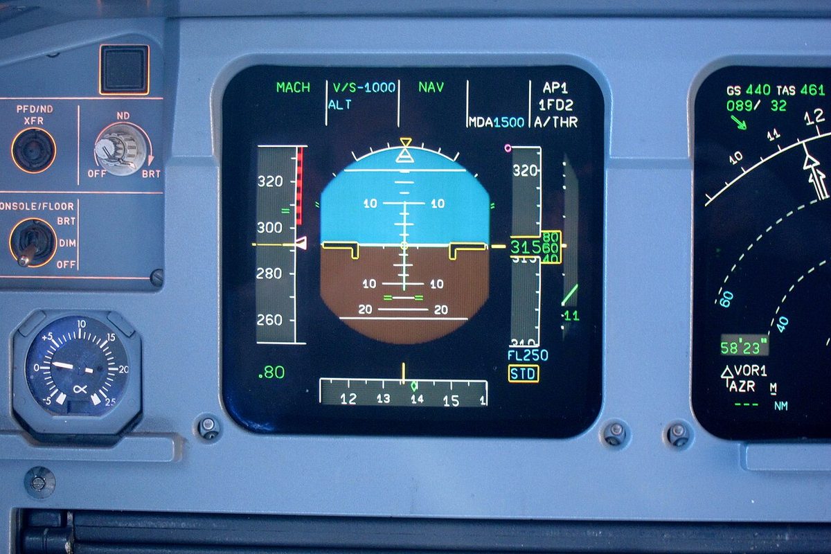
Several symbols are specific to the A320:
- Sideslip index (beta target). The sideslip index, normally yellow, turns blue and becomes a sideslip target when an engine fails at take-off or go-around, defined as CONF 1, 2 or 3 selected, any N1 above 80 % or one thrust lever above MCT, and the N1s more than 35 % apart. The FAC then shows the rudder needed for best climb performance, with ailerons neutral and spoilers retracted; the pilot centres the index.
- Tailstrike pitch limit indicator. From 400 ft radio height, a mark shows the maximum pitch attitude that avoids a tailstrike at landing, a fixed value for the main gear compressed. It disappears when the risk has passed.
- Flight path vector. With TRK-FPA selected by the HDG-V/S / TRK-FPA pushbutton on the flight control unit, both PFDs show the green flight path vector.
- Declutter. Beyond 45° of bank, everything except attitude, speed, heading, altitude and vertical speed disappears until the bank is back below 40°. Beyond 25° nose-up or 13° nose-down the same happens, the speed trend also remaining, until the pitch is back within 22° nose-up and 10° nose-down; beyond 30° red arrowheads point the way back.
Flags flash for 9 seconds and then stay steady, except V1 INOP, which is steady at once. At the transition altitude and level the barometric setting flashes on the PFD as a reminder to change it. During a TCAS resolution advisory the vertical speed scale shows red and green areas to avoid and to reach.
ND modes and overlays
The ND has five modes, chosen on the EFIS control panel: ROSE LS, ROSE VOR and ROSE NAV, each with a full compass rose, ARC, which gives the ROSE NAV information limited to the forward 90°, and PLAN. If the mode or range data fails, the ND defaults to ROSE NAV at 80 NM. When GPS PRIMARY is not available and the navigation accuracy is LOW on approach, at least one ND must be in ROSE LS or ROSE VOR.
Overlays add information in most modes:
- Weather radar, in every mode except PLAN.
- Terrain. A TERR ON ND pushbutton on each side of the ECAM screens puts the terrain picture on that pilot's ND, replacing the weather radar image. If a terrain awareness alert occurs with it not selected, terrain appears automatically and its ON light comes on; the display is deselected automatically when the TERR STBY memo appears.
- Traffic. The TCAS traffic display selector on the ATC/TCAS panel sets which intruders are shown. THRT shows proximate and other intruders only when a TA or RA is present; ALL shows them all the time, within 2,700 ft above and below; ABV extends other intruders to 9,900 ft above and BLW to 9,900 ft below. Proximate traffic is a white filled diamond, a TA an amber circle and an RA a red square, and only the eight most threatening intruders are shown. TCAS: REDUCE RANGE appears if a TA or RA occurs with a range above 40 NM, and TCAS: CHANGE MODE in PLAN.
- Bearing pointers for VOR 1 or ADF 1 and VOR 2 or ADF 2, chosen with the ADF/VOR switches, with the VOR DME distance; the DME of an ILS appears on the PFD.
EFIS control panel
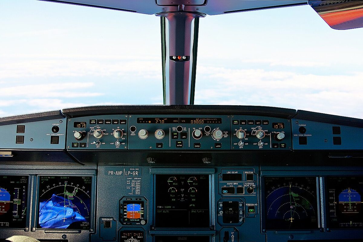
The flight control unit on the glareshield consists of three panels: the autoflight panel in the middle and an EFIS control panel at each end. Each EFIS control panel carries:
- the barometric reference knob: pulled for STD, pushed for QNH, with a QNH range of 745 to 1,100 hPa (22.00 to 32.48 inHg) and a default of 1,013 hPa or 29.92 inHg when the panel is powered up;
- the FD pushbutton, which engages or disengages that pilot's flight director;
- the LS pushbutton (landing system), which must also be selected to hear the DME audio of an ILS station (the standby instrument has an LS key of its own, which shows localiser and glide slope scales);
- the ND mode and range selectors and the two ADF/VOR switches;
- the overlay pushbuttons for database items on the ND.
Display transfer and reconfiguration
The EIS reconfigures itself where it can and lets the crew do the rest:
| Failure | What happens or what the crew does |
|---|---|
| PFD unit fails | The PFD image moves automatically to the ND unit beside it |
| Pilot wants the PFD on the other unit | Turn the PFD brightness knob to OFF, or press the PFD/ND XFR pushbutton to swap the two images |
| Upper ECAM screen fails or is switched off | The E/WD moves automatically to the lower screen; a system page can be shown on an ND with the ECAM/ND XFR selector, or on the remaining screen by holding its ECP key for up to 3 minutes |
| Lower ECAM screen fails | System and status pages on an ND with ECAM/ND XFR, or on the upper screen by holding the page key for up to 3 minutes |
| Both ECAM screens fail | ECAM/ND XFR puts the E/WD on an ND; holding a page key shows that system page there |
| DMC 1 or 2 fails | INVALID DATA on its screens; select CAPT 3 or F/O 3 on the EIS DMC selector. If DMC 1 (or DMC 3 at CAPT 3) fails, DMC 2 takes over the ECAM automatically |
Exam tip: PFD/ND XFR and ECAM/ND XFR move pictures between screens, which cures a failed display unit. A failed DMC needs the EIS DMC selector, and a failed ADR or IR the AIR DATA or ATT HDG selector.
Switching panel
The switching panel, on the pedestal just above the ECAM control panel, holds four rotary selectors:
| Selector | NORM | CAPT 3 | F/O 3 |
|---|---|---|---|
| ATT HDG | IR 1 supplies the captain's side, IR 2 the first officer's | IR 3 replaces IR 1 | IR 3 replaces IR 2 |
| AIR DATA | ADR 1 supplies the captain's side, ADR 2 the first officer's | ADR 3 replaces ADR 1 | ADR 3 replaces ADR 2 |
| EIS DMC | DMC 1 and DMC 2 as normal | DMC 3 replaces DMC 1 | DMC 3 replaces DMC 2 |
The fourth, ECAM/ND XFR, sends the system display to the captain's or first officer's ND. The ATT HDG, AIR DATA or EIS DMC selector at CAPT 3 or F/O 3, or a PFD/ND XFR pushbutton pressed while ECAM/ND XFR is at CAPT or F/O, brings up the SWITCHG PNL memo on the engine/warning display, so that an unusual configuration is not forgotten. The ADIRS side of the switching is described in A320 ADIRS and standby instruments.
Frequently asked questions
How many display management computers does the A320 have?
Three identical DMCs. Each has a single channel and can drive one PFD, one ND and both ECAM screens at the same time. Normally DMC 1 drives the captain's PFD and ND and the ECAM screens, DMC 2 the first officer's PFD and ND, and DMC 3 stands by. If DMC 1 or 2 fails, its screens show INVALID DATA and the crew selects CAPT 3 or F/O 3 on the EIS DMC selector.
What happens if a PFD fails on the A320?
The PFD image transfers automatically to the navigation display unit beside it. The pilot can make the same transfer by turning the PFD brightness knob to OFF, or swap the PFD and ND images with the PFD/ND XFR pushbutton. A failed display unit may show a blank screen with an amber F, a distorted picture or INVALID DISPLAY UNIT.
What are the navigation display modes on the A320?
There are five: ROSE LS, ROSE VOR and ROSE NAV, which show a full compass rose, ARC, which shows the ROSE NAV information limited to the forward 90 degrees, and PLAN. The weather radar image can be shown in every mode except PLAN. If the mode or range selection fails, the ND defaults to ROSE NAV at 80 NM.
What does the blue sideslip index mean on the A320 PFD?
Normally the sideslip index under the roll scale is yellow. It turns blue and becomes a sideslip target, the beta target, when an engine fails at take-off or go-around: CONF 1, 2 or 3 selected, an N1 above 80 % or a thrust lever above MCT, and N1 values more than 35 % apart. Centring it with rudder gives the best climb performance, with ailerons neutral and spoilers retracted.
What is the tailstrike pitch limit indicator on the A320?
It is a PFD symbol showing the maximum pitch attitude that avoids a tailstrike at landing, a fixed value corresponding to the main landing gear compressed. It appears at 400 ft radio height and disappears when there is no longer a risk of tailstrike. A tailstrike on take-off is followed by a return to the departure airport, avoiding any altitude that requires a pressurised cabin.
What does the SWITCHG PNL memo mean on the A320?
It reminds the crew that the switching panel is not in its normal configuration: the ATT HDG, AIR DATA or EIS DMC selector is at CAPT 3 or F/O 3, or a PFD/ND XFR pushbutton is pressed while the ECAM/ND XFR selector is at CAPT or F/O. It appears on the engine/warning display among the memos.
Test yourself on A320 EIS Displays and EFIS Controls
The v1prep banks cover this topic in the A320 type-rating bank, with a worked explanation for every answer. EASA ATPL, PPL, IR and CPL, the FAA written tests and A320/B737 type ratings.
Start practising →Sources and further reading
- FAA Advisory Circular AC 25-11B, Electronic Flight Displays
- EASA Easy Access Rules for Large Aeroplanes (CS-25), CS 25.1321 and AMC 25-11, Electronic flight deck displays
- EASA Type Certificate Data Sheet EASA.A.064, Airbus A318, A319, A320, A321
- FAA Instrument Flying Handbook (FAA-H-8083-15B), Chapter 5, Flight Instruments
- EASA, Explanatory Note to ED Decision 2018/001/R, Part-FCL theoretical knowledge learning objectives (022 Instrumentation)
Library articles are written for study and exam preparation. They do not replace your aircraft's approved documentation, your operator's procedures or the regulations themselves.