Navigation Displays and Indicators
Navigation displays and indicators show the aircraft's horizontal position relative to radio aids, courses and routes: from single-purpose instruments such as the relative bearing indicator, radio magnetic indicator and course deviation indicator to the horizontal situation indicator and the EFIS navigation display.
Navigation displays and indicators show where the aircraft is in the horizontal plane relative to radio aids, courses and routes. They fall into two families. Bearing instruments point at a station: the relative bearing indicator, the radio magnetic indicator and the bearing pointers of an HSI or navigation display. Deviation instruments show the displacement from a selected course: the course deviation indicator and the deviation bar of an HSI. The EFIS navigation display combines both with a moving map built by the flight management system.
The older instruments still matter. They appear in PPL, IR and ATPL exams, in the standby instruments of airliners, and in the rose modes of the navigation display, which reproduce them electronically. How the aids themselves work is covered under VOR, NDB and ADF and ILS.
Relative bearing indicator
The relative bearing indicator (RBI), or fixed-card ADF, has 000 permanently at the top. Its needle points at the NDB and reads the relative bearing, the angle measured clockwise from the nose to the station. To find the magnetic bearing to the station, the QDM, the pilot adds the magnetic heading and subtracts 360 if the total exceeds 360; the reciprocal is the QDR. With a heading of 300°(M) and a relative bearing of 136°, the QDM is 436 − 360 = 076° and the QDR 256°. The tail of a fixed-card needle, which here reads 316, is not the QDR.
A movable-card ADF lets the pilot turn the card by hand to the heading, after which the needle head reads the QDM; the card must be reset after every heading change.
Radio magnetic indicator
The radio magnetic indicator (RMI) removes the arithmetic. Its card is slaved to the aircraft's compass system or inertial heading, so it always shows the heading under the lubber line (see heading indicators and compass systems). Two bearing pointers, usually a single and a double needle, can each be switched to a VOR or an ADF receiver. For either kind of station:
- the head of the pointer reads the QDM, the magnetic bearing to the station;
- the tail reads the QDR, which for a VOR is the radial the aircraft is on;
- the relative bearing is the angle between the lubber line and the pointer head.
With the card at 250° and the ADF pointer head on 310°, the relative bearing is 060° and the QDR 130°. A VOR pointer head on 045° puts the aircraft on the 225 radial. To fly a DME arc, the pilot keeps the pointer close to the wingtip reference, letting it drift slightly behind and then turning towards the station to bring it slightly ahead. The A320's standby DDRMI follows the same pattern: its card is driven by ADIRU 1, the dashed pointer shows VOR 1 or ADF 1 and the double pointer VOR 2 or ADF 2.
Exam tip: on an RMI the head always reads QDM and the tail QDR, whatever the heading. On a fixed-card RBI only heading plus relative bearing gives the QDM.
Course deviation indicator
The course deviation indicator (CDI) works with the omni bearing selector (OBS). The pilot sets a course with the OBS; the needle shows the angular displacement of the aircraft from that course, and a TO/FROM flag shows whether that course, flown, leads towards or away from the station. Neither needle nor flag depends on heading. On a five-dot VOR CDI each dot is 2° and full scale is 10°. With a localiser tuned the OBS has no effect and the needle is about four times as sensitive, reaching full scale at about 2.5°.
A GPS navigator drives the CDI with a linear cross-track deviation instead: full scale is 5 NM en route (2 NM on a WAAS receiver), 1 NM in the terminal area and 0.3 NM in approach mode. On LPV and LNAV/VNAV approaches the scaling becomes angular, like a localiser.
The CDI acts as a command instrument only when the selected course roughly matches the direction of flight. Flown the other way it reverse senses, so the pilot must steer away from the needle; the same happens on a localiser back course.
Horizontal situation indicator
The horizontal situation indicator (HSI) combines a slaved heading card with the CDI. The course pointer, set with a course knob, turns with the card, and the deviation bar in its centre moves sideways across a dot scale, typically two dots each side at 5° per dot for a VOR. A TO/FROM arrow, a glideslope pointer at the side and warning flags complete the picture: a NAV flag when the VOR or localiser signal is unreliable, a GS flag for the glideslope, and a heading or power flag when the compass input or the instrument's power fails.
Because pointer and bar are drawn on the heading card, the HSI is a plan view of the aircraft relative to the course. With the correct course set it cannot reverse sense: the pilot steers towards the bar. With the course pointer on 090, heading 090, the bar left of centre and a FROM indication, the aircraft is east of the station and south of the 090 radial, and a turn towards the bar regains it. On a localiser the pilot always sets the published front course, even for a back course. Left on the reciprocal, the bar shows the right amount of deviation on the wrong side.
The heading bug, or selected heading bug, is a marker on the card set with the heading knob. It is the target of the autopilot and flight director heading mode, so moving it with that mode engaged starts a turn at once. On EFIS displays it is magenta and parks at the edge of the scale when the selected heading is out of view. Bearing pointers on an HSI read exactly as on an RMI.
Over-station sensing protects the autopilot near a VOR. The radials converge as the station is approached, the needle becomes ever more sensitive and over the cone of confusion it becomes erratic. When the system detects this, it decouples the roll channel from the beam and holds the drift-corrected heading existing at that moment; beyond the cone it recouples automatically in VOR mode.
Navigation display and EHSI
The electronic horizontal situation indicator (EHSI) of the first EFIS installations reproduced the HSI on a screen and added a map. Its successor, the navigation display (ND), takes heading and position from the inertial reference system, the route from the flight management computer, and raw data from the VOR, DME, ILS and ADF receivers, with TCAS traffic and weather radar returns overlaid. Typical Boeing symbols are:
- a triangle for the aircraft, with the current track drawn as a white line ahead of it;
- the selected heading bug, the course pointer and the deviation bar in magenta;
- the active route as a continuous magenta line and the active waypoint in magenta, the later waypoints of the route in white, off-route database waypoints and untuned navaids in cyan, and route changes not yet executed in short white dashes;
- a trend vector predicting the path 30, 60 and 90 seconds ahead from the present bank angle and groundspeed;
- groundspeed, true airspeed and wind in the top left corner.
In current airliners the ILS receiver sits in a multi-mode receiver (MMR), which also houses the GLS receiver and, on some installations, the GPS receiver. On the A320, PFD 1 and ND 2 show ILS data from MMR 1, and PFD 2 and ND 1 from MMR 2, so each pilot sees one receiver on the PFD and the other on the ND. On the 737 NG the VHF NAV transfer switch can set both pilots' displays to MMR 1, and the integrated standby flight display takes its localiser and glideslope from MMR 1.
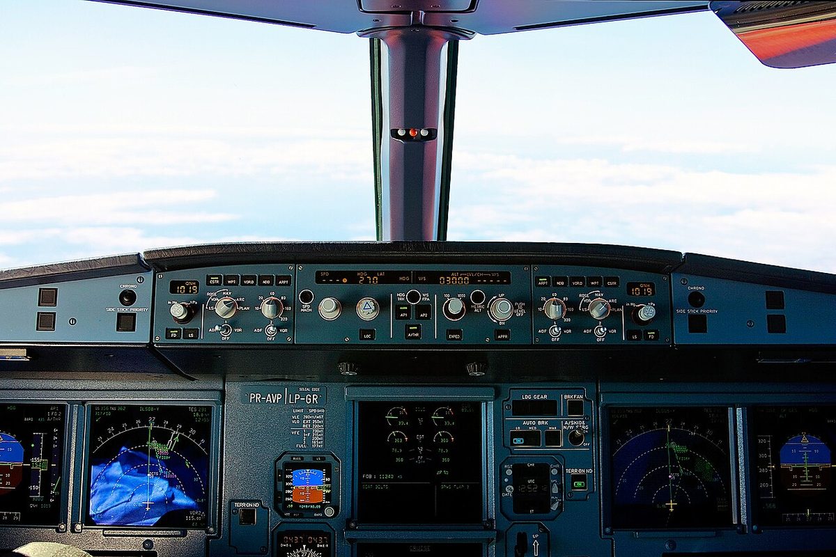
ND modes: ROSE, ARC and PLAN
The pilot selects the ND mode and range on the EFIS control panel (see EFIS). The names differ between manufacturers, but the pictures fall into three kinds.
| Picture | Classic Boeing EFIS and 737 NG | Airbus A320 |
|---|---|---|
| Full compass rose, aircraft in the centre, like an HSI | Full VOR and ILS (APP) modes; centred MAP on the 737 NG | ROSE LS, ROSE VOR, ROSE NAV |
| Forward sector, aircraft near the bottom, map ahead | Expanded VOR and ILS modes; MAP | ARC: ROSE NAV limited to the forward 90° |
| Static route map | PLAN | PLAN |
Overlays depend on the mode. In the classic Boeing EFIS described in ATPL texts, weather radar appears only in the expanded VOR and ILS modes and in MAP, never on the full rose or in PLAN. On the 737 NG weather, TCAS and terrain are not shown in centred APP mode or in PLAN. The A320 shows the weather radar in every mode except PLAN, and if its ND loses the mode or range selection it defaults to ROSE NAV at 80 NM.
The rose modes with a VOR or ILS selected show raw data in the classic HSI format, independent of the flight management system. Crews use them to monitor the FMS-built map, especially on approach.
Heading-up, track-up and north-up
A map must be oriented one way or another, and each choice shows drift differently.
- Heading-up: the heading is at the top and the track lies off to one side by the drift angle. Boeing's APP mode is heading-up, and so are the Airbus ARC and ROSE NAV modes, which show the track as a small diamond.
- Track-up: the current track is at the top and a pointer on the arc shows the heading. Boeing's MAP mode is track-up, so the magenta route line points straight up when the aircraft is on track, and the drift is the angle between the heading pointer and the top of the display.
- North-up: true north is at the top whatever the heading. PLAN mode is north-up and does not move: it is centred on a waypoint that the crew steps through on the FMC LEGS page to review the route and check a change before executing it. The aircraft symbol appears at its actual position when it is within the displayed range.
Turning a paper chart track-up has the same advantage as a track-up display: features appear on the same side as they do out of the window. Displays also carry a magnetic or true reference, M or MAG against TRU. In the EFIS described in ATPL texts, MAP mode references magnetic north between 73°N and 65°S and changes automatically to true north outside those latitudes; a MAG/TRUE selector can force true at any latitude.
Vertical situation display
The ND shows the horizontal picture. On the Boeing 737 NG the vertical situation display (VSD) adds a profile view of the aircraft and its environment along the current track. It shows in profile what lies within a corridor drawn on the ND map in cyan dashed lines, and its horizontal scale covers half the range selected for the ND.
On an approach the VSD draws the FMC approach glide path angle line where the procedure has a designated angle, or a 3° reference line where it has not, with decision gates on that line at 500 and 1,000 ft above field elevation. The 3° line is for reference only, and the FCOM warns that it may intersect terrain. A range-to-target-speed dot shows where the aircraft will reach the FMC or mode control panel target speed. Together these let the crew see in the vertical plane a descent path that is too steep or too shallow, or a deceleration begun too late, which a plan view cannot show (see stabilised approach).
Frequently asked questions
What is the difference between an RMI and an HSI?
An RMI is a bearing instrument: its card is slaved to the compass and its pointers aim at the tuned VOR or NDB, so the head reads the bearing to the station and the tail the radial or bearing from it. An HSI is mainly a deviation instrument: a slaved heading card with a course pointer and deviation bar showing displacement from a selected course. Many HSIs and navigation displays also carry RMI-style bearing pointers.
How do you read the radial from an RMI?
Read the tail of the pointer tuned to the VOR. The head gives the magnetic bearing to the station, the QDM, and the tail its reciprocal, the QDR, which is the radial the aircraft is on. A pointer head on 045 means the station bears 045 degrees and the aircraft is on the 225 radial. No heading arithmetic is needed, because the card is slaved to the compass system.
Why can an HSI not reverse sense?
The course pointer and deviation bar are drawn on the rotating heading card, so the display is always a plan view of the aircraft relative to the course, whichever way it is heading. Steering towards the bar always regains the course, provided the correct course is set. On a localiser that means the published front course, even when flying the back course; set the reciprocal and the bar appears on the wrong side.
What are the ND modes ROSE, ARC and PLAN?
ROSE modes show a full compass rose with the aircraft in the centre, like an HSI; on the A320 they come as ROSE LS, ROSE VOR and ROSE NAV. ARC shows the same navigation picture limited to the 90 degree sector ahead, with the aircraft near the bottom of the screen. PLAN is a static north-up map centred on a selected waypoint, used to review the route. Boeing's equivalents are the full and expanded VOR and APP modes, MAP and PLAN.
What is the difference between heading-up and track-up on a navigation display?
On a heading-up display the aircraft's heading is at the top and the track appears off to one side by the drift angle; Airbus ARC and ROSE NAV modes work this way. On a track-up display, such as Boeing's MAP mode, the current track is at the top and a pointer on the arc shows the heading, so the route line points straight ahead when the aircraft is on track. PLAN mode is north-up.
Test yourself on Navigation Displays and Indicators
The v1prep banks cover this topic in Instrumentation (022), with a worked explanation for every answer. EASA ATPL, PPL, IR and CPL, the FAA written tests and A320/B737 type ratings.
Start practising →Sources and further reading
- FAA Instrument Flying Handbook (FAA-H-8083-15B), Chapter 9, Navigation Systems
- FAA Pilot's Handbook of Aeronautical Knowledge (FAA-H-8083-25), Chapter 16, Navigation
- FAA Aeronautical Information Manual, Chapter 1 Section 1, Air Navigation Aids
- EASA, Explanatory Note to ED Decision 2018/001/R, Part-FCL theoretical knowledge learning objectives (022 Instrumentation, 062 Radio Navigation)
Library articles are written for study and exam preparation. They do not replace your aircraft's approved documentation, your operator's procedures or the regulations themselves.