A320 ADIRS and Standby Instruments
The A320 Air Data and Inertial Reference System (ADIRS) consists of three identical air data and inertial reference units (ADIRUs). Each combines an air data reference (ADR) and an inertial reference (IR) that can work separately, and supplies air data, attitude, heading and position to the displays, flight controls, FMGCs, engines and other systems.
The A320's Air Data and Inertial Reference System (ADIRS) tells every other system how fast the aircraft is flying, how high it is, which way up it is and where it is. Three identical air data and inertial reference units (ADIRUs) do the work, each combining an air data computer and an inertial reference system. Their data feed the displays, the fly-by-wire computers, the flight management and guidance computers, the engines and many more, so a fault in the ADIRS reaches well beyond the instruments.
When the air data itself becomes doubtful, the crew falls back on the standby instruments, which share a probe with ADIRU 3, and on a known pitch and thrust. The principles are in air data computer and air temperature, inertial reference system alignment and modes and unreliable airspeed.
ADIRS architecture
Each ADIRU has two parts, the air data reference (ADR) and the inertial reference (IR), and either can work if the other fails. Their users include the EFIS displays, the FMGCs, the FADECs, the flight control computers (ELAC, SEC and FAC), the flight warning computers, the slat and flap control computers, the transponder, the GPWS and the cabin pressure controllers.
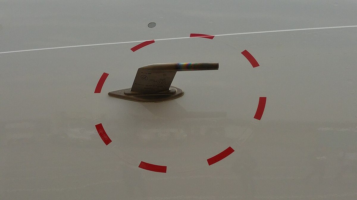
The air data comes from three pitot probes (captain, first officer and standby), six static ports, three angle-of-attack sensors and two total air temperature (TAT) probes, all electrically heated; probe heating comes on automatically once an engine is running or the aircraft is airborne. Eight air data modules (ADMs) turn the pitot and static pressures into digital data.
| ADIRU | Fed by | Normally supplies |
|---|---|---|
| 1 | Captain's probes | Captain's PFD and ND, the DDRMI and the VOR/DME |
| 2 | First officer's probes | First officer's PFD and ND |
| 3 | Standby probes and the captain's TAT probe | Either side, when selected |
The standby pitot and static sources also feed the standby instruments directly, so ADR 3 and the standby airspeed use the data of the same probe. Their agreement is not independent proof.
Two GPS receivers, separate units or built into the multi-mode receivers, feed the ADIRUs: GPS 1 supplies ADIRUs 1 and 3, GPS 2 supplies ADIRU 2, and if one fails all ADIRUs use the other. Each ADIRU computes a hybrid GPS and inertial position (GPIRS), which the FMGCs use. The FMGCs compute their own position from GPS, the IRSs (as the mixed IRS position, MIX IRS) and DME-DME, VOR-DME or LOC-DME radio updating, blending the sources with a priority logic (see FMS navigation and position updating).
The ADIRUs keep running on battery power if normal power fails, and the ON BAT light on the ADIRS panel shows that at least one is on batteries. On the ground an external horn sounds at the same time and ADIRU and AVNCS lights come on amber at the external power panel; both are inhibited in flight.
Air data reference
The ADR supplies barometric altitude, airspeed, Mach number, angle of attack, temperature and overspeed warnings. The flight control laws use ADR data, and the system display shows TAT and SAT among its permanent data. Each ADR has its own pushbutton on the ADIRS panel, which the crew uses to remove a faulty ADR without losing the IR of the same unit. Air data also reaches ATC: the transponder sends airspeed, Mach and barometric vertical speed from the ADRs.
Inertial reference and IR mode selector
The IR supplies attitude, flight path vector, track, heading, accelerations, angular rates, ground speed and position. Each ADIRU has an IR mode selector on the overhead ADIRS panel:
| Position | Effect |
|---|---|
| NAV | Normal mode: full inertial data, after alignment |
| ATT | Attitude, and heading if the crew enters it on the MCDU, to be reset about every 10 minutes; no navigation data |
| OFF | The whole ADIRU is de-energised: IR and ADR data are both lost |
Set from NAV to ATT or OFF in flight, an IR loses its NAV mode for the rest of the flight, which is why the pilots cross-check before touching an IR mode selector. A flashing IR FAULT light means attitude and heading may be recovered in ATT mode; a steady one means the IR is lost.
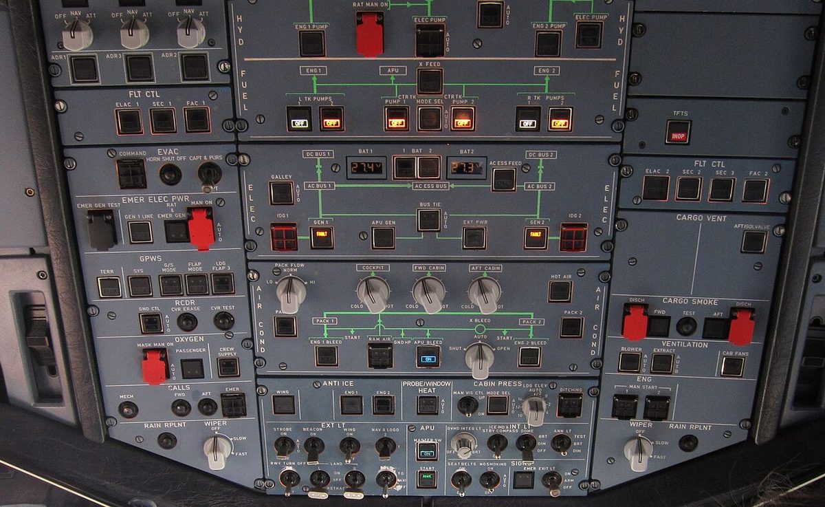
An IR can be aligned only with the aircraft stopped, not during engine start or with the engines running, and if the aircraft moves a new full alignment is needed. Ground alignment is possible between 82° N and 82° S.
- A complete alignment sets the selectors OFF for more than 5 seconds, then NAV. The IRSs use gravity and the earth's rotation to find attitude and true heading and estimate the latitude, and the ON BAT light comes on for a few seconds at the start. It is required before the first flight of the day, at a crew change, at a departure airport between 2° N and 2° S, and with GPS unavailable if navaid coverage is poor or the flight will exceed 3 hours.
- A fast alignment sets them OFF and back to NAV within 5 seconds. The IRSs reset ground speed and some filters but do not estimate position. It is needed, when a complete alignment is not, if the IRS and FMGC positions differ by 5 NM or more on the MCDU POSITION MONITOR page.
The crew initialises the position, preferably with the gate coordinates. During alignment in flight phases 1 and 2 the E/WD shows IRS IN ALIGN with the minutes remaining, from 10 down to 1: green, pulsing if one IRS's alignment is faulty, and amber once an engine has started, when a faulty alignment becomes the IR NOT ALIGNED caution. IR IN ATT ALIGN shows an alignment in attitude mode. After parking the pilot monitoring checks the IRS performance on the POSITION MONITOR page against published limits, and when the aircraft is secured the crew waits at least 10 seconds after setting the selectors OFF before removing power, so that the ADIRS can store the latest data.
Magnetic heading comes from variation tables in the ADIRUs. With identical tables, the IRs give no valid magnetic heading or track north of 73° N between 90° W and 120° W, north of 82° N or south of 60° S, and flight beyond these limits is prohibited.
ATT HDG and AIR DATA switching
The ATT HDG and AIR DATA selectors on the switching panel, on the pedestal, replace a failed source with ADIRU 3. At NORM ADIRU 1 supplies the captain's side and ADIRU 2 the first officer's. At CAPT 3, IR 3 or ADR 3 replaces IR 1 or ADR 1; at F/O 3, it replaces IR 2 or ADR 2. When ADIRU 3 is selected on the ATT HDG selector, it also positions the DDRMI compass card. Any position other than NORM brings up the SWITCHG PNL memo. The display side of the panel is covered in A320 EIS displays and EFIS controls.
Standby instruments and DDRMI
The A320 carries an integrated standby instrument system (ISIS) in the centre panel, fed by the standby pitot and static sources. It shows attitude, airspeed and Mach number, altitude, the barometric setting, landing system deviation scales and speed and altitude bugs, but no wind. Its pitch scale is marked every 2.5° between 30° nose-up and 30° nose-down, with red chevrons beyond, and its bank scale at 0°, 10°, 20°, 30°, 45° and 60°. Mach appears above M 0.5 and disappears below M 0.45. Pressing the BARO knob selects STD.
- The LS key shows localiser and glide slope scales, which must not be used for a take-off on the opposite runway's localiser or a back course approach, because the localiser deviation would be reversed.
- The ATT RST key, pressed for at least 2 seconds with the aircraft level, resets the attitude in about 10 seconds; a reset is required after 350 hours of continuous power.
- Flags: a red ATT flag shows attitude lost; WAIT ATT becomes ATT: RST after 10 seconds; a white MAINT flag on the ground does not affect operation.
- The bugs are not recommended: if both PFDs were lost, take-off speed bugs could be left in place for the approach.
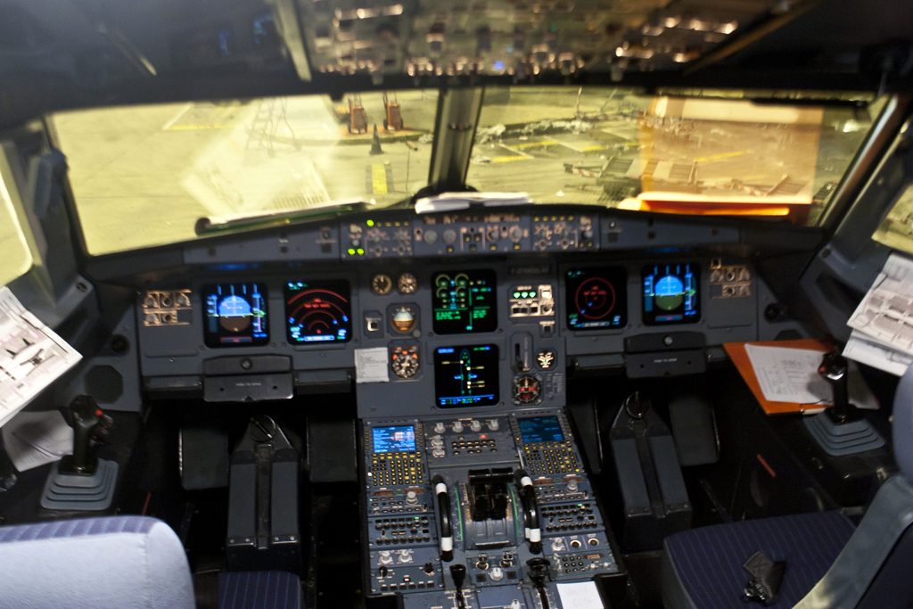
Some aircraft, such as the early A320-211 in the photo below, have separate round electromechanical standby instruments instead, a standby horizon among them. Whichever is fitted, the standby altimeter is set with the main altimeters at the transition altitude and level. A standby magnetic compass sits on the windshield centre post, with its deviation card above it; the APU start sequence may disturb its reading.
The distance/direction radio magnetic indicator (DDRMI) combines a compass card, normally driven by ADIRU 1, with two bearing pointers and two DME counters. The dashed pointer shows VOR 1 or ADF 1 and the double pointer VOR 2 or ADF 2. The counters show whole nautical miles above 20 NM and tenths below, and 0 inside 1 NM. A VOR/ADF flag shows a receiver failure and a HDG flag lost heading.
Unreliable airspeed: tables and BUSS
The UNRELIABLE SPEED INDICATION memory items apply when the safe conduct of the flight is affected. The crew disconnects the autopilot, autothrust and flight directors and sets a known pitch and thrust: 15° and TOGA below the thrust reduction altitude, 10° and CLB above it up to FL100, and 5° and CLB above FL100. The flap configuration is kept, except that CONF FULL goes to CONF 3; the speedbrakes are checked retracted, the landing gear is selected up, and the stall warning is always respected.
At or above the minimum safe or circuit altitude the crew levels off for troubleshooting and uses the QRH pitch and thrust tables. The technique is to hold the altitude: if the pitch is above the table value, the aircraft is slow, so thrust is increased, and if it is below, thrust is reduced, until the pitch settles on the target.
The affected ADR is then sought, starting with PROBE/WINDOW HEAT ON. If one ADR is confirmed reliable, it is used and the unreliable ADR pushbuttons are set OFF. If the faulty ones cannot be identified, above FL250 one ADR stays on and two go off, so that the flight control laws cannot act on two coherent but unreliable sources. Below FL250, if the speed is still unreliable, all three ADRs go off and the NAV ADR 1+2+3 FAULT procedure is applied. On the A321XLR that condition gives direct law at once.

Where fitted, the backup speed scale (BUSS) then replaces the speed scale on both PFDs. It is computed from angle of attack and the slat and flap configuration, and the crew flies the green band. GPS altitude replaces barometric altitude, with amber dashes over the last two digits and a GPS ALT flag, and vertical speed is no longer shown. The selection cannot be reversed. If the BUSS does not respond to pitch inputs, it is disregarded and the pitch and thrust tables are used.
Warning: ADR 3 and the standby instruments use the same probe. Two sources that agree, or the standby that agrees with one PFD, may be wrong together; pitch, thrust and the stall warning remain the reference.
Frequently asked questions
What does each part of an A320 ADIRU supply?
The air data reference (ADR) supplies barometric altitude, airspeed, Mach number, angle of attack, temperature and overspeed warnings. The inertial reference (IR) supplies attitude, flight path vector, track, heading, accelerations, angular rates, ground speed and position. The two parts can work separately, so an ADR can be switched off while its IR keeps running, but setting the IR mode selector to OFF de-energises the whole ADIRU.
What is the difference between a complete and a fast IRS alignment on the A320?
For a complete alignment the IR mode selectors are set OFF for more than 5 seconds, then to NAV: the IRSs find attitude and true heading from gravity and the earth's rotation and estimate latitude. For a fast alignment they go OFF and back to NAV within 5 seconds: the IRSs reset ground speed and some filters but do not estimate position. A fast alignment is done when no complete alignment is needed but the IRS and FMGC positions differ by 5 NM or more.
What happens if an A320 IR mode selector is moved from NAV in flight?
If an IR mode selector is set from NAV to ATT or to OFF in flight, the NAV mode of that IR is lost for the rest of the flight. In ATT mode the IR gives attitude and heading only, and the heading must be entered on the MCDU and reset about every 10 minutes. The pilots must cross-check before moving an IR mode selector in flight.
What do the ATT HDG and AIR DATA selectors do on the A320?
They are on the switching panel on the pedestal. At NORM, ADIRU 1 supplies the captain's PFD and ND, the DDRMI and the VOR/DME, and ADIRU 2 the first officer's displays. At CAPT 3, IR 3 or ADR 3 replaces IR 1 or ADR 1 on the captain's side; at F/O 3 it replaces IR 2 or ADR 2. Any selection other than NORM brings up the SWITCHG PNL memo.
What is the BUSS on the A320?
The backup speed scale, fitted on some aircraft, replaces the PFD speed scale when the crew switches off all three ADRs during an unreliable speed procedure. It is computed from angle of attack and slat and flap configuration, and the crew flies within its green band. GPS altitude replaces barometric altitude and vertical speed is no longer shown. The selection cannot be reversed, and if the BUSS does not respond to pitch inputs the pitch and thrust tables are used.
Why are two ADRs switched off above FL250 in the A320 unreliable speed procedure?
If the faulty ADRs cannot be identified, or all are affected, above FL250 the crew keeps one ADR on and switches two off. This stops the flight control laws from using two coherent but unreliable air data sources, which could outvote the good one. Below FL250, if the speed is still unreliable, all three ADRs go off and the BUSS takes over where fitted.
Test yourself on A320 ADIRS and Standby Instruments
The v1prep banks cover this topic in the A320 type-rating bank, with a worked explanation for every answer. EASA ATPL, PPL, IR and CPL, the FAA written tests and A320/B737 type ratings.
Start practising →Sources and further reading
- FAA Aeronautical Information Manual, Chapter 1 Section 1 (1-1-15, IRU, INS and AHRS)
- EASA Easy Access Rules for Large Aeroplanes (CS-25), CS 25.1323 Airspeed indicating system and CS 25.1325 Static pressure systems
- 14 CFR 25.1325, Static pressure systems
- Airbus Safety First, Unreliable Airspeed at Takeoff
- BEA, Final Report on the accident on 1 June 2009 to the Airbus A330-203, flight AF 447
- EASA Type Certificate Data Sheet EASA.A.064, Airbus A318, A319, A320, A321
- EASA, Explanatory Note to ED Decision 2018/001/R, Part-FCL theoretical knowledge learning objectives (022 Instrumentation)
Library articles are written for study and exam preparation. They do not replace your aircraft's approved documentation, your operator's procedures or the regulations themselves.