A320 Characteristic Speeds
The A320 characteristic speeds are the reference speeds shown on the PFD speed scale, most of them computed by the flight augmentation computers from the aircraft's weight and configuration: VLS, the stall warning and protection speeds, green dot, S and F, with the VFE limits and VFE NEXT.
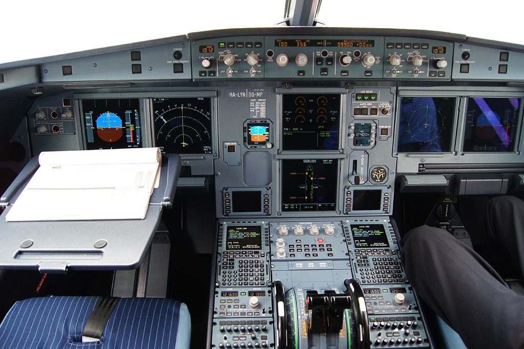
On many older airliners the crew take their manoeuvring speeds from tables or cards and set bugs on the airspeed indicator. On the A320 the aircraft does it for them. Two flight augmentation computers work out a family of characteristic speeds from the aircraft's weight and configuration, and the PFD draws them on the speed scale together with the speed limits: the lowest speed the crew may select, the speeds at which slats and flaps may be retracted, the best clean speed, the limits of the current and next configuration and, when the protections are lost, the stall warning speed.
These speeds are the A320 pilot's working references from take-off to touchdown. They tell the crew when to clean up after take-off and when to configure on approach, they bound the autoflight system's speed targets, and the final approach speed is built on one of them. Their definitions and the rules of thumb behind them are standard type rating questions. The general background is in structural and operating speed limits and approach speeds.
Where characteristic speeds come from
The flight augmentation computers (FACs) compute VLS, F, S and green dot, the characteristic speeds shown on the PFD. Flight envelope functions, which include the PFD speed scale and alpha floor, are one of the FAC's four main tasks, beside yaw control, the low-energy aural alert and windshear detection. The FACs also compute VαPROT, VαMAX and VSW, but only for display: the protections themselves are activated by the elevator aileron computers (ELACs), which work from angle of attack. The speeds on the MCDU take-off and approach pages are computed by the flight management system (FMS) instead, apart from V1, VR and V2, which the crew insert on the take-off page. The A321neo XLR has no FACs, so its architecture differs.
Most characteristic speeds are multiples of the stall speed (VS) of a given configuration, which depends on weight, so they move as fuel is burned and whenever the configuration changes.
| Speed | Meaning | Use |
|---|---|---|
| VLS | Lowest selectable speed | Floor for speed targets; base of VAPP |
| VαPROT, VαMAX | Angle of attack protection speeds (normal law) | Display of the high angle of attack protection |
| VSW | Stall warning speed | Shown when normal law is lost |
| Green dot | Engine-out operating speed, clean | Best clean speed, expedite climb, approach |
| S | Minimum slat retraction speed | Take-off clean-up; CONF 1 target on approach |
| F | Minimum flap retraction speed | Take-off clean-up; CONF 2 and 3 target |
| VFE, VFE NEXT | Limits of current and next configuration | Upper speed limits |
VLS and VSW
VLS, the lowest selectable speed, keeps a margin above the stall in every configuration. It is:
- 1.13 VS during take-off or after a touch-and-go;
- 1.23 VS once the flaps have been retracted one step;
- 1.28 VS in the clean configuration (at 1.23 VS the alpha protection strip on the speed scale would touch the VLS strip).
Above 20,000 ft VLS is corrected for Mach so that it keeps a 0.2 g buffet margin, which links it to the buffet boundary described in buffet boundaries and maximum altitude. VLS also rises when the speedbrakes are extended. In the clean configuration, VLS with full speedbrakes can be higher than green dot or the VFE of flap 1, so the crew make sure there is a speed margin before extending the speedbrakes and before starting a turn with them out, to avoid triggering alpha floor.
The autoflight system respects VLS. If the crew select too high a vertical speed in a climb and the speed falls to VLS, the vertical speed target is disregarded and VLS is held. With the autopilot off, the flight director on and the autothrust at idle in a descent mode, the flight director bars disappear at VLS − 2 kt and the autothrust engages its SPEED mode.
In normal law the bottom of the speed scale shows the high angle of attack protection: an amber and black strip marks VαPROT, the speed corresponding to the angle of attack at which the protection starts, and VαMAX lies below it (see A320 flight control laws and protections). When normal law is lost, these give way to VSW, the stall warning speed, drawn as a red and black strip. In alternate law with reduced protection an artificial low speed stability, starting about 5 to 10 kt above VSW, gently pushes the nose down, and the stall warning, a cricket sound with a STALL synthetic voice and a red STALL STALL message on the PFD, comes in at a margin from the stall. Amber crosses replace the green protection symbols on the PFD whenever protections are lost.
Green dot speed
Green dot is the engine-out operating speed in the clean configuration, close to the speed for the best lift-to-drag ratio. A rule of thumb gives an approximate value:
- below 20,000 ft: green dot ≈ 2 × weight in tonnes + 85 kt;
- above 20,000 ft: add 1 kt per 1,000 ft.
At 60 t, for example, green dot is about 2 × 60 + 85 = 205 kt.
Exam tip: "2 × weight + 85" is green dot below FL 200. Add 1 kt per 1,000 ft above it, so at 70 t and FL 300 green dot is about 2 × 70 + 85 + 10 = 235 kt.
Green dot appears throughout the flight:
- Climb. It is the speed of the maximum climb gradient, the shortest distance to a level, and the target speed of expedite climb (EXP CLB). The best rate of climb lies between ECON climb speed and green dot.
- Cruise and holding. At high altitude the crew should not slow below green dot, because the extra drag may exceed the available thrust. The default holding speed, when no limit applies, is the maximum endurance speed, which is about green dot.
- Engine failure. Green dot is the clean engine-out speed. After an engine failure, LVR MCT flashes on the FMA when the speed is above green dot and the remaining thrust lever is not at MCT.
- Approach. Flaps 1 is selected at green dot, more than 3 NM before the final descent point.
S and F speeds
S speed is the minimum speed at which the slats may be retracted after take-off. It is about 1.22 to 1.25 times the clean stall speed. F speed is the minimum speed at which the flaps may be retracted after take-off, about 1.18 to 1.22 times the stall speed in CONF 1+F.
After take-off in CONF 2 or 3, the crew retract to 1 at F speed with the aircraft accelerating, a positive speed trend, and to 0 at S speed, again accelerating. After a CONF 1+F take-off only the second step remains. The protections described in A320 slats and flaps back this up: the automatic retraction system retracts the flaps of CONF 1+F at 210 kt, and the alpha/speed lock keeps the slats out if flaps 0 is selected at too low a speed.
On approach the same speeds become targets. S is the target speed in CONF 1 and F the target in CONF 2 and CONF 3. In a decelerated approach, the standard technique for ILS and similar approaches, the aircraft usually reaches the final descent point in CONF 1 at S speed and must be established on the final descent with flaps 1 and S speed at or above 2,000 ft AGL, then reach 1,000 ft in the landing configuration at VAPP. To decelerate smoothly, the crew select the next configuration when the speed reaches the manoeuvring speed of the current one plus 10 kt, provided the speed is below the next VFE: CONF 1 at green dot + 10 kt, for example. This gives about 10 kt per NM in level flight, and about 20 kt per NM with speedbrakes.
VFE and VFE NEXT
VFE is the maximum speed for the current slat and flap configuration; VFE NEXT is the maximum speed for the next, further extended lever position. Showing VFE NEXT on the speed scale tells the pilot at a glance whether the next configuration may be selected.
| Configuration | CONF 1 | CONF 1+F | CONF 2 | CONF 3 | CONF FULL |
|---|---|---|---|---|---|
| A320 VFE | 230 kt | 215 kt | 200 kt | 185 kt | 177 kt |
The top of the speed scale shows VMAX, the maximum speed in the current configuration, as a red and black strip. The other limits are VMO 350 kt and MMO M 0.82, and VLE, the limit with the landing gear extended, 280 kt or M 0.67. VMAX follows the flaps lever, while the overspeed warning follows the actual slat and flap position, so a brief overspeed warning during a configuration change has no consequence. In its speed and Mach modes the autothrust limits the speed to VMAX with slats or flaps extended and to VMAX − 5 kt in the clean configuration, whatever the target. The A321's VFEs are different, so A320 family pilots fly the limits on the PFD rather than remembered figures.
VAPP and ground speed mini
VREF, the reference speed for a normal final approach, is 1.23 VS in CONF FULL and is shown on the MCDU approach page when a CONF FULL landing is planned. The final approach speed VAPP is built on VLS of the landing configuration. The FMS computes:
VAPP = VLS + the greater of 5 kt and one third of the tower headwind component, the wind correction being limited to 15 kt.
With a VLS of 130 kt and a tower headwind component of 24 kt, VAPP is 130 + 8 = 138 kt; in calm wind or with a tailwind it is 135 kt. VAPP must not be less than VLS + 5 kt with autoland, with the autothrust engaged, with ice accretion or in a gusty crosswind above 20 kt, and in strong or gusty crosswinds above 20 kt the crew may raise the increment up to 15 kt.
Ground speed mini then adjusts the managed speed target during the approach. Its principle is that the aircraft's energy relative to the ground should not fall below what it would have at VAPP in the tower wind, because a gust that suddenly dies leaves the aircraft with its ground speed, not its airspeed. The target becomes:
target = VAPP + (current headwind − tower headwind), bounded by VAPP and VFE NEXT.
If the tower headwind was 24 kt and the aircraft meets 40 kt on final, the target rises by 16 kt; if the headwind then falls back to the tower value near the ground, the extra speed is lost but the aircraft is still at VAPP. Ground speed mini works only with managed speed. Characteristic speeds also bound the go-around speed: SRS targets the higher of VAPP and the speed at go-around engagement, up to the lower of VLS + 25 kt (VLS + 15 kt with one engine inoperative) and VMAX − 5 kt.
Exam tip: the FACs compute the characteristic speeds on the PFD; the FMS computes the speeds on the MCDU take-off and approach pages; the ELACs, not the FACs, activate the protections.
Frequently asked questions
What is VLS on the A320?
VLS is the lowest selectable speed, the lowest speed the crew can select and the reference for approach speed. It is 1.13 times the stall speed at take-off or after a touch-and-go, 1.23 times after the first step of flap retraction and 1.28 times in the clean configuration. Above 20,000 ft it is corrected for Mach to keep a 0.2 g buffet margin, and it rises when the speedbrakes are extended.
How is A320 green dot speed calculated?
Green dot is the engine-out operating speed in the clean configuration, close to the best lift-to-drag ratio. The flight augmentation computers compute it, but a rule of thumb gives it below 20,000 ft as twice the weight in tonnes plus 85 kt, so about 205 kt at 60 t. Above 20,000 ft add 1 kt for every 1,000 ft. It is the target speed of expedite climb and close to the best holding speed.
What are S and F speeds on the A320?
They are the minimum speeds for retracting the high-lift devices after take-off. At F speed, accelerating, the crew retract the flaps from 2 or 3 to 1; at S speed they retract to 0. On approach, S is the target speed in CONF 1 and F the target in CONF 2 and 3. S is about 1.22 to 1.25 times the clean stall speed and F about 1.18 to 1.22 times the stall speed in CONF 1+F.
How does the A320 FMS compute VAPP?
The FMS takes VLS of the landing configuration and adds the greater of 5 kt and one third of the headwind component of the tower wind, the wind correction being limited to 15 kt. VAPP may not be less than VLS plus 5 kt with autoland, with autothrust engaged, with ice accretion or in a gusty crosswind above 20 kt. VREF, 1.23 times the CONF FULL stall speed, is shown separately.
What is ground speed mini on the A320?
Ground speed mini is the managed approach speed function that keeps the aircraft's energy when the wind changes on final. The target becomes VAPP plus the difference between the current headwind and the tower headwind, never less than VAPP and never more than VFE NEXT. In a gust the indicated speed target rises, so the ground speed does not fall below the value expected at VAPP.
Test yourself on A320 Characteristic Speeds
The v1prep banks cover this topic in the A320 type-rating bank, with a worked explanation for every answer. EASA ATPL, PPL, IR and CPL, the FAA written tests and A320/B737 type ratings.
Start practising →Sources and further reading
- EASA Type Certificate Data Sheet EASA.A.064, Airbus A318, A319, A320, A321 (airspeed limits)
- EASA Easy Access Rules for Large Aeroplanes (CS-25), CS 25.103, 25.125 and 25.1505
- 14 CFR 25.125, Landing
- Airbus, Safety innovation
- EASA, Explanatory Note to ED Decision 2018/001/R, Part-FCL theoretical knowledge learning objectives
Library articles are written for study and exam preparation. They do not replace your aircraft's approved documentation, your operator's procedures or the regulations themselves.