A320 Autothrust and Thrust Levers
On the A320 the autothrust (A/THR) controls engine thrust between idle and a limit set by the thrust lever position, either to hold a target speed or to give a fixed thrust. The thrust levers are not moved by the system: each detent selects a thrust rating limit that the FADEC applies.
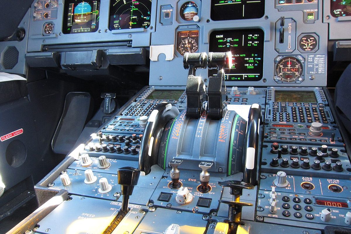
The A320's thrust levers do two jobs. Set by hand, they select a thrust rating limit that the FADEC applies, from idle to take-off/go-around thrust; within the autothrust range, their position becomes the ceiling of what the autothrust (A/THR) may command. Unlike a Boeing autothrottle, the A/THR never moves the levers. The autothrust commands come from the flight guidance part of the flight management and guidance computers (FMGCs), and the FADECs turn them into fuel flow.
Most of the logic below is common to the A320 family. Thrust figures and EGT limits are those of the CFM56-5B. The engines themselves are described in A320 engines and FADEC and the general principles in autothrottle.
Non-back-driven thrust levers
There is no mechanical linkage between the thrust levers and the engines. Each lever's position is sensed electrically and sent to its FADEC as a thrust lever angle, which the FADEC treats as the crew's intent. Airbus chose non-back-driven thrust levers so that the crew judge the aircraft's energy from current cues, speed, speed trend and engine parameters, rather than from levers that move by themselves.
The levers belong to the pilot flying. If an ECAM, QRH or OEB procedure calls for a lever action, the pilot flying points to the lever, the pilot monitoring confirms, and the pilot flying moves it. During the take-off the captain keeps a hand on the levers until V1. Reverse, behind the idle stop, is reached by lifting the reverser latching levers on the front of the thrust levers.
Detents and thrust rating limits
Each thrust lever has four forward detents, TOGA, FLX/MCT, CL and IDLE, and carries an instinctive disconnect pushbutton. For each position the FADEC computes an N1 rating limit (an EPR limit on the V2500), shown in green on the engine/warning display, with the thrust limit mode and any FLEX temperature in blue. A lever set between two detents gets the limit of the higher detent. The limits available depend on the situation:
| Situation | Rating limits available |
|---|---|
| Engines running, on the ground | TOGA, FLEX, CL, MREV |
| In flight, or on the ground with engines stopped | TOGA, MCT or FLEX, CL, MREV |
MCT is therefore not available on the ground with the engines running, and there the displayed limit is TOGA whatever the lever position, unless a FLEX temperature is entered, when it is the FLEX N1 up to the FLX/MCT detent. The CL detent gives climb thrust (CLB), the maximum for the climb. TOGA may be used for 5 minutes with all engines operating and 10 minutes with one inoperative, with an EGT limit of 950 °C; MCT is not time-limited, at 915 °C. MREV is maximum reverse.
Only FLX/MCT and TOGA are approved for take-off. The pilot flying sets about 50 % N1 (1.05 EPR) and then the chosen detent, and the pilot monitoring checks that each engine has reached its rating limit before 80 kt and calls "thrust set".
Some engines have a thrust bump function. On the A320-214, for example, modification 38946 introduces it and the CFM56-5B4 becomes the CFM56-5B4/P1, and the type certificate data sheet does not allow bump and non-bump engines to be mixed on one aircraft. The A320's published VMCA of 110 kt and VMCG of 111 kt in CONF 1+F at sea level are the values without thrust bump.
Flexible take-off thrust
Turbofans are flat rated: they give their full rated thrust up to a flat-rating temperature, TREF, and less above it. A flexible take-off exploits this. The crew enter an assumed temperature, the flexible temperature (TFLEX), on the MCDU PERF TAKE OFF page, and the FADEC gives the thrust the engine would produce at that temperature. TFLEX may not be:
- higher than the maximum flexible temperature (TMAXFLEX), ISA + 53 °C;
- lower than TREF;
- lower than the actual outside air temperature.
FLEX is not permitted on a contaminated runway, and it may not be combined with a derated take-off. A derate is a lower certified rating; during a derated take-off TOGA may not be selected unless an abnormal or emergency procedure calls for it, and a derate may be used on dry, wet or contaminated runways (see reduced and derated take-off thrust).
Warning: with no FLEX temperature entered, the FLX/MCT detent gives TOGA thrust on the ground, without any warning. Changing the FLEX temperature during the take-off roll has no effect: the rating set at the start of the roll is kept.
FLEX performance assumes an engine failure at V1 with FLX thrust on the remaining engine, so no lever action is needed; TOGA remains available. The rating changes from FLX to MCT only when the lever is moved to TOGA or CL and back to FLX/MCT, normally at green dot speed when LVR MCT flashes. Moving the lever out of the detent without reaching TOGA or CL changes nothing, and once MCT has been set, FLX is no longer available for the rest of the flight.
Autothrust arming and activation
The A/THR is always in one of three states: armed, ready to take over; active, controlling thrust; or disconnected. Arming needs at least one FMGC, one flight augmentation computer (FAC), two ADIRUs, two FADECs, one flight control unit channel and one landing gear control interface unit, and the A/THR must not have been disabled by the crew. With no autopilot or flight director engaged, FMGC 1 controls the A/THR.
With both engines running the A/THR is active with the levers between just above idle and the CL detent; with one engine, between idle and MCT. Within that range the lever position sets the highest thrust the A/THR may command. Beyond it, in FLX/MCT or TOGA, the A/THR is armed but not active, and thrust is the manual rating of the detent, shown on the FMA as MAN TOGA, MAN FLX or MAN MCT.
A take-off therefore starts with the A/THR armed. At the thrust reduction altitude, 1,500 ft by default unless the operator sets another value, LVR CLB flashes on the FMA, and when the pilot flying brings the levers back to CL the A/THR becomes active. A go-around repeats the pattern: TOGA, then CL at the go-around thrust reduction altitude.

SPEED/MACH and THRUST modes
The A/THR mode depends on what the autopilot or flight director does with the pitch:
| A/THR mode | When | What thrust does |
|---|---|---|
| SPEED or MACH | The vertical mode controls the flight path: altitude capture and hold, V/S, G/S, FINAL APP | Varies to hold the target speed or Mach |
| THR CLB | SRS, CLB, OP CLB, EXP CLB or SRS GA, most forward lever in CL | Fixed at climb thrust; pitch holds the speed |
| THR MCT | The same climb modes with the most forward lever at MCT, typically one engine out | Fixed at MCT |
| THR IDLE | DES, OP DES, EXP DES, or RETARD | Fixed at idle |
In managed descent the A/THR may be in THR IDLE on the idle path or in SPEED on a geometric segment. RETARD is available only in an automatic landing; the RETARD callout comes at 10 ft radio altitude in autoland and at 20 ft in a manual landing, and the A/THR disconnects when both levers reach idle.
In SPEED or MACH the A/THR never targets more than VMAX in a high-lift configuration, or VMAX − 5 kt clean. Below 3,200 ft radio altitude in CONF 1 or more it is more responsive above 150 ft and less responsive below, to avoid a long flare. The A/THR also protects the speed when the flight director is used without the autopilot: in a THR IDLE descent the flight director bars disappear at VLS − 2 kt, and in a THR CLB climb at VMAX + 4 kt, and the A/THR reverts to SPEED. When an A/THR thrust change is in progress, the N1 command arc on the N1 gauge shows the target N1 the needle is moving towards.
Disconnection and thrust lock
The standard disconnection uses the A/THR instinctive disconnect pushbutton on either lever. Held for more than 15 seconds, it disables the A/THR for the rest of the flight, alpha floor included, until the FMGCs are next powered up on the ground. Setting both levers to IDLE also disconnects it, as in the flare of a manual landing; a pilot who lands with manual thrust disconnects the A/THR by 1,000 ft above aerodrome level at the latest. The unreliable speed memory items set the A/THR OFF, after the autopilot, and in an emergency descent without A/THR the levers go to IDLE.
After a non-standard or involuntary disconnection, the thrust lock function freezes the thrust at its value before the disconnection. THR LK flashes on the FMA, and if the levers are not moved within 5 seconds ENG THRUST LOCKED appears on the ECAM, with a single chime and MASTER CAUT repeated every 5 seconds. Moving the levers ends the lock and gives manual thrust from the lever position.
Alpha floor and TOGA LK
Alpha floor is an autothrust function of the FACs' flight envelope protection. When the angle of attack becomes very high, between alpha prot and alpha max, it commands TOGA thrust whatever the lever position and the A/THR state, from lift-off down to 100 ft radio altitude on approach. The FMA shows A.FLOOR, and speedbrake extension is inhibited. When the condition has cleared and the speed is above VLS, the FMA shows TOGA LK in a flashing amber box and thrust stays at TOGA. The crew cancel it with the instinctive disconnect pushbutton once a safe speed is regained, then set the levers for the thrust they want.
Alpha floor is lost when the A/THR has been disabled for the flight, and in alternate law (see A320 flight control laws and protections). Extending the speedbrakes raises VLS, so crews keep a speed margin before using them, which also avoids triggering alpha floor.
Low energy warning
The low energy warning is the synthetic voice "SPEED, SPEED, SPEED", computed by the FACs. It sounds when the thrust is no longer enough to recover a positive flight path through pitch control alone, and repeats every 5 seconds until the thrust levers are advanced. It works in CONF 2, 3 and FULL and is inhibited above 2,000 ft and below 100 ft radio altitude, with TOGA selected, during alpha floor or a GPWS alert, in alternate or direct law, and with both radio altimeters failed.
Thrust lever messages
| Message | Where | Meaning and action |
|---|---|---|
| LVR CLB (flashing) | FMA | Above the thrust reduction altitude, both engines running, levers not in CL: set CL |
| LVR MCT (flashing) | FMA | Engine failed, remaining lever not in MCT, speed above green dot: set MCT |
| LVR ASYM (amber) | FMA | One lever in FLX/MCT or TOGA, the other between IDLE and CL: match the levers |
| THR LK (flashing) | FMA | Thrust frozen after a non-standard disconnection: move the levers |
| A.FLOOR, TOGA LK | FMA | Alpha floor active, then TOGA locked: disconnect the A/THR at a safe speed |
| ENG THRUST LOCKED | ECAM | Levers not moved within 5 seconds of an involuntary disconnection |
| ENG THR LEVERS NOT SET | ECAM | Take-off configuration warning, triggered by take-off power, not by the T.O CONFIG test |
| RETARD | Voice | Levers not at IDLE or reverse at 20 ft (10 ft in autoland) |
| RETARD, RETARD | Voice | After touchdown, one lever above IDLE while the other is at IDLE or reverse |
The levers matter elsewhere too. The ground spoilers extend only with both levers at or below idle, or reverse selected; speedbrake extension is inhibited with a lever above MCT; and on the ground the autopilot disengages if all levers are set above the MCT detent.
Frequently asked questions
Why do the A320 thrust levers not move with the autothrust?
Airbus chose non-back-driven thrust levers. Each lever position sets a thrust rating limit, and within the autothrust range the position is the maximum thrust the A/THR may command. The crew judge the aircraft's energy from speed, speed trend and engine parameters rather than from lever movement. In normal flight with both engines running, the levers are set to the CL detent, the top of the autothrust range, at the thrust reduction altitude.
What happens if the levers are set to FLX/MCT without a FLEX temperature?
On the ground, with no flexible temperature entered in the MCDU, the FLX/MCT detent gives TOGA thrust, not a reduced thrust, and no ECAM warning is given. The take-off is therefore made at full thrust. The crew must check the FLEX temperature on the PERF TAKE OFF page and its display on the engine/warning display before take-off. Changing the FLEX temperature during the take-off roll has no effect on thrust.
What is alpha floor on the A320?
Alpha floor is an autothrust protection that commands TOGA thrust, whatever the thrust lever position and the A/THR state, when the angle of attack becomes very high. It is available from lift-off to 100 ft radio altitude on approach. When the condition has cleared and the speed is above VLS, the FMA shows TOGA LK: thrust stays at TOGA until the crew disconnects the autothrust with the instinctive disconnect pushbutton.
What is thrust lock (THR LK) on the A320?
After a non-standard autothrust disconnection, such as one caused by a failure, the thrust stays frozen at its value before the disconnection. THR LK flashes on the FMA and, if the thrust levers are not moved within 5 seconds, ENG THRUST LOCKED appears on the ECAM with a single chime and MASTER CAUT every 5 seconds. Moving the levers ends the lock and gives manual thrust.
What does LVR CLB mean on the A320 FMA?
LVR CLB flashes on the FMA when the aircraft is above the thrust reduction altitude with both engines running and the thrust levers are not in the CL detent. It reminds the pilot flying to bring the levers back from FLX/MCT or TOGA to CL, where the autothrust becomes active. After an engine failure the equivalent reminder is LVR MCT, shown above green dot speed when the remaining lever is not in MCT.
When does the A320 give the SPEED SPEED SPEED low energy warning?
The flight augmentation computers trigger it when thrust is not sufficient to recover a positive flight path by pitch control alone. It repeats every 5 seconds until thrust is increased. It works in CONF 2, 3 and FULL and is inhibited above 2,000 ft and below 100 ft radio altitude, with TOGA selected, during alpha floor or a GPWS alert, in alternate or direct law, and with both radio altimeters failed.
Test yourself on A320 Autothrust and Thrust Levers
The v1prep banks cover this topic in the A320 type-rating bank, with a worked explanation for every answer. EASA ATPL, PPL, IR and CPL, the FAA written tests and A320/B737 type ratings.
Start practising →Sources and further reading
- EASA Type Certificate Data Sheet EASA.A.064, Airbus A318, A319, A320, A321
- FAA AC 25-13, Reduced and Derated Takeoff Thrust (Power) Procedures
- EASA Easy Access Rules for Large Aeroplanes (CS-25), CS 25.1329 Flight guidance system
- 14 CFR 25.1329, Flight guidance system
- Airbus, Safety innovation
- FAA Airplane Flying Handbook (FAA-H-8083-3C), Transition to Jet-Powered Airplanes
- EASA, Explanatory Note to ED Decision 2018/001/R, Part-FCL theoretical knowledge learning objectives (022 Instrumentation)
Library articles are written for study and exam preparation. They do not replace your aircraft's approved documentation, your operator's procedures or the regulations themselves.