Landing Gear Layouts and Shock Absorbers
The landing gear supports an aircraft on the ground, lets it manoeuvre and absorbs the energy of landing. Its layout fixes where the wheels sit relative to the centre of gravity, and its shock absorbers, on most aircraft oleo-pneumatic struts, cushion and damp the touchdown.
The landing gear, or undercarriage, is the part of an aircraft that meets the ground. It carries the whole weight when the aircraft is parked, steers and brakes it on the ground, and absorbs the energy of each landing, then spends the rest of the flight as dead weight. Its design is a compromise between those jobs and the cost in mass and drag of carrying it aloft.
Two choices shape every landing gear: the layout, meaning how many legs there are and where they stand relative to the centre of gravity (CG), and the shock absorber, which decides how the landing energy is taken out. How retractable gear is raised, locked and lowered is covered in landing gear retraction and extension, and steering in nose wheel steering.
Landing gear functions
ATPL texts give the landing gear three functions:
- To let the aircraft manoeuvre on the ground: taxiing, the take-off run and the landing roll.
- To support it at a convenient height, giving clearance for propellers, flaps and doors and easing loading.
- To absorb the kinetic energy of landing and provide a means of controlling deceleration, through the shock absorbers and the brakes.
The loads it carries are varied: compression from the static weight and the impact of touchdown, rearward bending as the wheels spin up on contact, side loads in crosswind landings and turns, forward loads in pushback, and torsion from steering and manoeuvring. Transport aeroplane gear is designed to absorb a touchdown at a vertical speed of 10 ft/s (3.05 m/s) at the maximum landing mass, and a heavy or overweight landing requires an inspection that starts with the landing gear and its attachments (see structural design and design loads). Some landing gear components are safe-life parts, retired after a fixed number of cycles whatever their condition.
Tricycle and tailwheel layouts
A tricycle layout has a nose landing gear (NLG) under the forward fuselage and two main landing gears (MLG) a short distance behind the CG. The mains carry most of the weight; the nose gear carries a much smaller share but must also steer, castor and resist towing loads. The aeroplane sits nearly level, giving the pilot a good view, and because the CG is ahead of the main wheels a swing on the ground tends to straighten itself. Almost all modern aircraft use this layout: the A320 has two twin-wheel main gears and a twin-wheel steerable nose gear, and so does the Boeing 737.
A tailwheel layout, also called conventional gear, has the two main wheels ahead of the CG and a small wheel, or on early aeroplanes a skid, under the tail. The tailwheel aeroplane sits nose-high, so the view ahead on the ground is poor, and with the CG behind the main wheels it is directionally unstable on the ground: if it begins to swing, the inertia of the mass behind the main wheels tightens the swing instead of damping it. Unchecked, the swing becomes a ground loop, a sharp turn in which a wingtip may strike the ground or a gear leg collapse (see lateral and directional stability). Raising the tail on the take-off roll also brings a gyroscopic swing from the propeller (see propeller torque and slipstream effects).
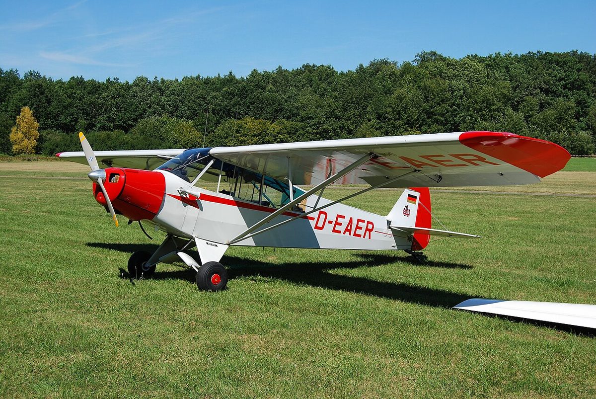
Pilots therefore need specific training for tailwheel aeroplanes. Under EASA's FCL.710 a tailwheel is one of the features that call for differences training within the single-engine piston class, and the FAA requires a tailwheel endorsement under 14 CFR 61.31; FAA day currency in a tailwheel aeroplane also requires the landings to be made to a full stop.
| Tricycle | Tailwheel | |
|---|---|---|
| CG position | Ahead of the main wheels | Behind the main wheels |
| Ground attitude | Nearly level | Nose-high |
| Directional stability on the ground | Stable, tends to straighten | Unstable, risk of ground loop |
A different kind of tail skid survives on airliners: it protects the rear fuselage in an over-rotation or a tail strike. The 737's has a shoe that contacts the runway, mounted on a cartridge of crushable honeycomb; a decal on the cartridge shows green and red while it is serviceable and all red once the cartridge has been crushed enough to need replacing.
Fixed and retractable gear
Fixed landing gear is simple, cheap to build and needs little maintenance, but its drag in flight costs speed and fuel. It is accepted on slow light aircraft, where the drag penalty is small, and on rugged types such as crop sprayers and short take-off aircraft.
Retractable landing gear folds into the wing or fuselage after take-off and removes that drag, at the cost of weight, complexity and maintenance: actuators, locks, doors, sequencing and position indication. The benefit outweighs the cost on any aircraft fast enough for the drag to matter, which is why almost every transport aeroplane retracts its gear. Retractable gear is also a differences-training item under EASA and part of the FAA complex aeroplane endorsement.
Main and nose gear structure
A main gear leg is built round a shock strut, attached to the wing or fuselage structure at its upper end and carrying the axle, wheels and brakes at its lower end. It takes the heaviest ground loads: most of the weight, the touchdown impact, the braking torque and the side loads of turns and crosswinds. High-strength steel is used where strength matters more than weight, and titanium for some highly stressed parts. Gear geometry varies: most airliner legs are straight telescopic struts, but the E190-E2, for example, has trailing-arm main gears, in which the wheels are carried on a pivoted arm behind the leg.
The nose landing gear is lighter, because it carries less weight and is loaded mainly in direct compression. It has its own demands: it must castor freely when towed, centre itself before retraction, steer, resist shimmy, and take the shear loads of pushback. A nose-wheel-first landing loads it in ways it is not designed for and can damage the strut, the drag link and the front pressure bulkhead, which is why an aeroplane should touch down on its main wheels first.
Bogies, track and wheelbase
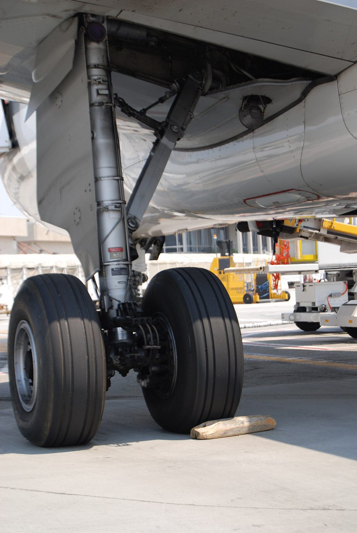
A light aircraft has one wheel on each leg and an airliner such as the A320 or 737 two. Heavier aircraft spread their weight over more tyres by mounting four or more wheels on a bogie: a beam pivoted at the foot of the leg, carrying pairs of wheels one behind the other. More tyres put less load on each, so the aircraft can use a given pavement at a higher mass; how hard an aircraft loads a pavement is reported by its aircraft classification rating (see aerodrome physical characteristics). The largest types, such as the Boeing 747 and Airbus A380, add main gears under the fuselage, the body gears, which steer to help them turn.
Two dimensions describe the layout. The main gear track is the distance across the aircraft between the main gears, measured to the outer wheels; the wheelbase is the distance along it from the nose gear to the main gear. The A320 family shows how they work. All three models share a track of 7.59 m, but the wheelbase is 11.04 m on the A319, 12.64 m on the A320 and 16.91 m on the A321, because the fuselage sections added or removed ahead of the wing change the distance to the nose gear. The longer wheelbase widens the turning circle: the minimum theoretical pavement width for a 180° turn in Airbus's airport planning data is 20.64 m for the A319, 22.90 m for the A320 and 27.6 m for the A321.
Oleo-pneumatic shock absorbers
The oleo-pneumatic shock strut, usually called an oleo strut, is the standard shock absorber of retractable and many fixed gears. Oleo refers to the oil, pneumatic to the gas. An outer cylinder attached to the airframe contains a sliding inner cylinder or piston, which carries the axle. The strut is partly filled with hydraulic fluid and the rest is charged with compressed gas, nitrogen or dry air.
On touchdown the strut shortens as the inner cylinder telescopes into the outer one:
- Damping: the fluid is forced through a small orifice, which limits how fast the piston can move. The energy of the landing is absorbed as heat in the fluid.
- Springing: the gas is compressed into a smaller volume, and its pressure rises until it balances the load.
After the impact the compressed gas pushes the strut back out, at a rate limited by the flow back through the orifice. Combining a gas spring with an oil damper makes the oleo the most efficient shock absorber in common use.
Standing still, the aircraft's weight is carried by the gas pressure, with the strut part-way along its travel. The visible length of shiny chrome-plated piston is the walk-round check. Too little chrome, or none, means the strut has lost gas or fluid, and touchdown loads will pass almost directly into the structure; too much means the gas pressure is too high; unequal readings on the two main gears show that one strut needs servicing. The maintenance manual gives the correct extension. Proximity sensors on the struts also detect whether they are compressed, which gives the aircraft its air/ground signal.
Metering pins and recoil valves
A plain orifice gives the same restriction throughout the stroke. A metering pin, or metering rod, makes the damping progressive. It is a tapered rod fixed in the strut that passes through the orifice, so that as the strut compresses the thicker part of the pin enters the orifice and reduces its effective area. The force-stroke curve can be tuned to absorb the landing energy evenly over the available travel.
Without control of the return stroke, the compressed gas would push the strut back out violently and bounce the aircraft. A recoil valve, or flutter valve, is a one-way restrictor in the strut: it lets the fluid flow freely as the strut compresses but restricts the flow as it extends, so the strut recovers slowly. That prevents a rapid rebound, a bounce or wheel hop on touchdown and over uneven ground.
Some struts keep the gas and fluid apart with a free-floating separator piston. Gas mixing into the fluid makes it foam and changes the damping, and fluid in the gas space reduces the spring's effectiveness; the separator prevents both. Struts without one are simpler but more prone to aeration.
Exam tip: in an oleo the gas is the spring and carries the static weight; the oil through the orifice is the damper and turns energy into heat. The metering pin varies the orifice during compression; the recoil (flutter) valve slows the extension.
Torque links and drag struts
An oleo's inner cylinder is free to rotate inside the outer one. Torque links, or scissor links, two arms hinged together and to the two cylinders, stop it: they fold and unfold as the strut compresses and extends but keep the wheel aligned with the leg. On a nose gear they connect the wheel to the steering. Worn or broken torque links allow rotational play and are a classic cause of nose wheel shimmy, together with worn wheel bearings, unequal tyre pressures and a faulty shimmy damper.
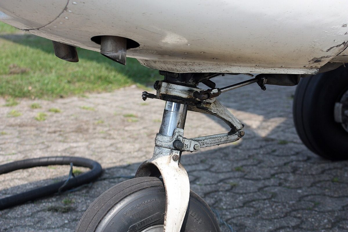
The leg also needs bracing against the drag loads that bend it rearwards at touchdown and the side loads of turns. A drag strut braces it fore and aft and a side stay sideways. On retractable gear these braces are built in two hinged halves that fold as the leg retracts. At full extension the hinge goes slightly past the straight line, over-centre, against a stop, so that the loads on the leg push it harder against the stop instead of folding it. That geometric lock holds the gear down without any hydraulic pressure.
Spring-steel and bungee gear
Light aircraft with fixed gear often use simpler absorbers. ATPL texts list three main types for fixed gear: the oleo, the spring-steel leg and the rubber cord.
- A spring-steel landing gear leg is a tapered strip or tube of spring steel that flexes as the aircraft lands and springs back afterwards. Many single-engine Cessnas use it.
- A bungee, or rubber cord shock absorber, uses turns of rubber cord that are loaded as the gear deflects; it is typical of the Piper Cub and similar types.
Less common systems use rubber blocks in compression, coil springs or liquid springs. A spring stores the landing energy and gives most of it back, with little damping of its own; an oleo turns the energy into heat, which is why the oleo is preferred wherever the energy to be absorbed is large.
Frequently asked questions
How does an oleo strut work?
An oleo-pneumatic strut is a cylinder and sliding piston containing hydraulic fluid and compressed nitrogen or dry air. On touchdown the strut shortens: the fluid is forced through a small orifice, which slows the piston and turns the landing energy into heat, while the gas is compressed until its pressure balances the load. The gas then acts as a spring that carries the aircraft's weight, and the restricted flow back through the orifice stops it rebounding.
What is the difference between tricycle and tailwheel landing gear?
A tricycle layout has a nose wheel and two main wheels just behind the centre of gravity. The aeroplane sits level and tends to run straight on the ground, which is why almost all modern aircraft use it. A tailwheel, or conventional, layout has its main wheels ahead of the centre of gravity and a small wheel or skid under the tail. Any swing on the ground tends to grow, and if it is not stopped early it can become a ground loop.
What do torque links do on an aircraft landing gear?
Torque links, also called scissor links, are two hinged arms that join the outer cylinder of an oleo strut to its sliding inner cylinder. They fold and unfold as the strut compresses and extends, but stop the inner cylinder rotating, so the wheels stay aligned with the leg and, on a nose gear, with the steering. Worn torque links allow rotational play and are a classic cause of nose wheel shimmy.
What is the wheelbase and the main gear track of an aircraft?
The wheelbase is the distance along the fuselage between the nose gear and the main gear; the main gear track is the distance across the aircraft between the main gears, usually measured to the outer wheels. On the A320 family the track is 7.59 m on every model, while the wheelbase is 11.04 m on the A319, 12.64 m on the A320 and 16.91 m on the A321, so the A321 needs much more pavement to turn.
Why does an oleo strut show more or less chrome?
The exposed chrome-plated part of the inner cylinder shows how far the strut is extended under the aircraft's weight. A correctly serviced strut shows the length given in the maintenance manual. Too little chrome means the strut has lost gas pressure or fluid and sits low, so landing loads pass almost straight into the structure. Too much chrome means the gas pressure is too high. Unequal readings on the two main gears show that one strut needs servicing.
Test yourself on Landing Gear Layouts and Shock Absorbers
The v1prep banks cover this topic in Aircraft General Knowledge (021), with a worked explanation for every answer. EASA ATPL, PPL, IR and CPL, the FAA written tests and A320/B737 type ratings.
Start practising →Sources and further reading
- FAA Aviation Maintenance Technician Handbook, Airframe (FAA-H-8083-31B), Chapter 13, Aircraft Landing Gear Systems
- FAA Pilot's Handbook of Aeronautical Knowledge (FAA-H-8083-25), Chapter 7, Aircraft Systems
- FAA Airplane Flying Handbook (FAA-H-8083-3C), Transition to Tailwheel Airplanes
- 14 CFR 25.473, Landing load conditions and assumptions
- EASA Easy Access Rules for Large Aeroplanes (CS-25), Subpart C, Structure, and Subpart D, Landing gear
- EASA, Explanatory Note to ED Decision 2018/001/R, Part-FCL theoretical knowledge learning objectives (021 Airframe and Systems)
Library articles are written for study and exam preparation. They do not replace your aircraft's approved documentation, your operator's procedures or the regulations themselves.