Hydraulic Pumps and Power Sources
Hydraulic power sources are the pumps and stores that pressurise an aircraft's hydraulic systems: engine-driven and electric motor-driven pumps for normal use, air-driven pumps, a ram air turbine, power transfer units and hand pumps for back-up, and gas-charged accumulators that hold fluid under pressure.
A hydraulic system is only as available as its pressure. Transport aircraft therefore generate it in several independent ways, store some of it for moments of peak demand or failure, and can pass power from one system to another without mixing their fluids. Losing a pump or even a whole system should cost capability, not control.
This article covers the pumps, accumulators, the valves that off-load or isolate a pump, and cavitation. Fluids, reservoirs and filters are described in hydraulic system principles and fluids.
- Hydraulic power sources
- Constant-delivery and constant-pressure pumps
- Engine-driven and electric motor pumps
- Air-driven pumps and the RAT
- Hand pumps, the PTU and standby systems
- Accumulators and pre-charge
- Pump off-loading and cut-out valves
- Hydraulic fire shut-off valves
- Pump cavitation
- Frequently asked questions
Hydraulic power sources
The pump types found on aircraft are:
- the engine-driven pump (EDP), the primary source on most transport aircraft;
- the electric motor-driven pump (EMDP), called an electric pump by Airbus and an AC motor pump (ACMP) by Embraer, used as a back-up and for ground operation;
- the air-driven pump (ADP), a pump turned by an air turbine motor running on bleed air;
- the ram air turbine (RAT), an emergency source;
- the power transfer unit (PTU), which borrows power from another system;
- the hydraulic hand pump, for ground servicing on large aircraft.
A ground service coupling (GSC) lets a ground test rig pressurise a system for checks, leak tests and gear retraction tests without running the engines or the APU.
| A320 | 737 NG | E190-E2 | |
|---|---|---|---|
| Systems | Green, blue, yellow | A, B, standby | 1, 2, 3 |
| Engine-driven pumps | Green (engine 1), yellow (engine 2) | A (engine 1), B (engine 2) | Systems 1 and 2 |
| Electric pumps | Blue, yellow | A, B, standby | 1, 2, and two in system 3 |
| Emergency and other | RAT (blue), hand pump (yellow) | Standby system, brake accumulator | RAT, system 3 accumulator |
| PTU | Green and yellow, either direction | System A power to system B | System 1 power to system 2 |
Normal operating pressure is 3,000 psi on all three types.
Constant-delivery and constant-pressure pumps
A constant delivery pump (fixed volume), typically a single or double stage gear pump, delivers the same flow whatever the demand. Surplus fluid must go back to the reservoir through an automatic cut-out valve or a relief valve, and an idling circuit is needed when no service is working. It is simple, and suits the lower pressures and modest loads of smaller aircraft, typically about 1,500 psi.
A constant pressure pump (variable volume), also called a variable displacement pump, regulates its own output to hold system pressure, typically 3,000 to 4,000 psi. Pistons in a cylinder block turned by the drive shaft ride on shoes against a stationary yoke, and the yoke angle sets their stroke: a larger angle means a longer stroke and more flow, a smaller angle less. When services move, the pump increases its flow; when nothing moves, output drops to a small flow that lubricates and cools the pump. No energy is wasted pushing surplus fluid through a relief valve, which is why transport aircraft use it.
A depressurising valve (off-load valve) lets a constant-pressure pump idle. When its solenoid is energised, it blocks delivery to the system and the pump output falls to a low pressure while fluid keeps circulating for lubrication and cooling; the accumulator meanwhile holds system pressure. The 737's engine pump switches use the same idea: OFF energises a blocking valve in the pump to block its output and ON de-energises it, which is why Boeing recommends leaving them ON at shutdown to prolong solenoid life. An engine-driven pump selected off still turns with the engine. On the E190-E2, an EDP cannot be stopped or disconnected from the gearbox at all; it is taken out of its system only by closing its shutoff valve.
Constant-pressure pumps have a case drain line, whose filter is inspected for metal particles to monitor pump wear.
Engine-driven and electric motor pumps
The engine-driven pump (EDP) on the accessory gearbox supplies most of the flow. On the 737 an engine-driven pump supplies about six times the fluid volume of the related electric motor-driven pump.
An electric motor pump (EMP), electric motor-driven pump (EMDP) or simply electric hydraulic pump is driven by an AC motor. It backs up the engine pumps, pressurises systems on the ground with the engines stopped, and on some aircraft is the main source of a system:
- On the A320 an electric pump on AC bus 1 is the normal source of the blue system. In AUTO it runs in flight, or on the ground when an engine is running or the maintenance override is pressed. The yellow electric pump, on AC bus 2, gives yellow pressure on the ground and starts automatically when a cargo door selector is operated.
- On the 737 NG each of systems A and B has an EMDP (ELEC 2 powers system A, ELEC 1 system B). An amber OVERHEAT light means the pump or its cooling fluid has overheated; on some variants power is then removed from the pump.
- On the E190-E2 system 3 has no engine pump and is pressurised by electric pump 3A, with 3B as its automatic back-up.
An electro-hydraulic power pack, or hydraulic power pack, is a self-contained unit with its own reservoir, pump, electric motor, valves and filters. It serves a single subsystem, such as a cargo door.
Air-driven pumps and the RAT
An air-driven pump (ADP) is a hydraulic pump turned by an air turbine motor (ATM) running on engine bleed air. It gives an alternate source for redundancy, and it can be run on the ground from an external air supply.
The ram air turbine (RAT) is a small turbine that drops out of the fuselage on a strut into the airstream. The slipstream turns it to drive a hydraulic pump, a generator or both, for the essential services only. It deploys automatically when the normal sources fail, or when the crew select it. Its output depends on airspeed.
On the A320 the RAT extends automatically when AC bus 1 and AC bus 2 are both lost above 100 kt, and at any time with the RAT MAN ON pushbutton. It pressurises the blue system at 2,500 psi instead of 3,000 psi, and the blue system drives the emergency generator through a hydraulic motor. The RAT can be stowed only on the ground. On the E190-E2, the system 3 accumulator keeps the flight controls powered from the start of RAT deployment until the AC essential bus powers electric pump 3A again, and unloader and flow limiter valves stop the pump overloading the RAT.
Hand pumps, the PTU and standby systems
A hydraulic hand pump on a large aircraft serves ground work: operating cargo doors without main hydraulic power, ground servicing and pressure testing. It is usually double-acting, delivering fluid on both strokes, with built-in non-return valves and a relief valve set about 10 % above normal system pressure. The A320's yellow system has one for the cargo doors when no electrical power is available. A hand pump usually draws from the bottom of the reservoir, below the stack pipe, so it keeps a reserve after a leak.
The power transfer unit (PTU) is a hydraulic motor coupled to a hydraulic pump. One system drives the motor, and the pump pressurises another, so power is transferred without fluid, and the systems stay isolated.
- On the A320 the PTU is bidirectional between green and yellow, and runs automatically when their pressures differ by more than 500 psi. It is inhibited during the first engine start and tested automatically during the second.
- On the 737 NG it uses system A pressure to power a pump that pressurises system B fluid, supplying the volume needed to run the leading edge flaps, slats and autoslats at the normal rate when the system B engine pump has failed. On most variants it runs automatically when that pump's pressure is low, airborne, with flaps less than 15 but not up.
- On the E190-E2 it transfers pressure from system 1 to system 2 during take-off and landing after an engine 2 or EDP 2 failure, keeping the landing gear and nose wheel steering available.
A standby hydraulic system provides a last reserve. The 737's standby system has its own reservoir and a single electric motor-driven pump, and powers the thrust reversers, the rudder through a standby power control unit, the leading edge flaps and slats (extend only) and the standby yaw damper. It is selected manually, or starts automatically after loss of system A or B with the flaps extended, the aircraft airborne or above 60 kt wheel speed and the related flight control switch ON, or when the main rudder PCU force fight monitor trips.

Accumulators and pre-charge
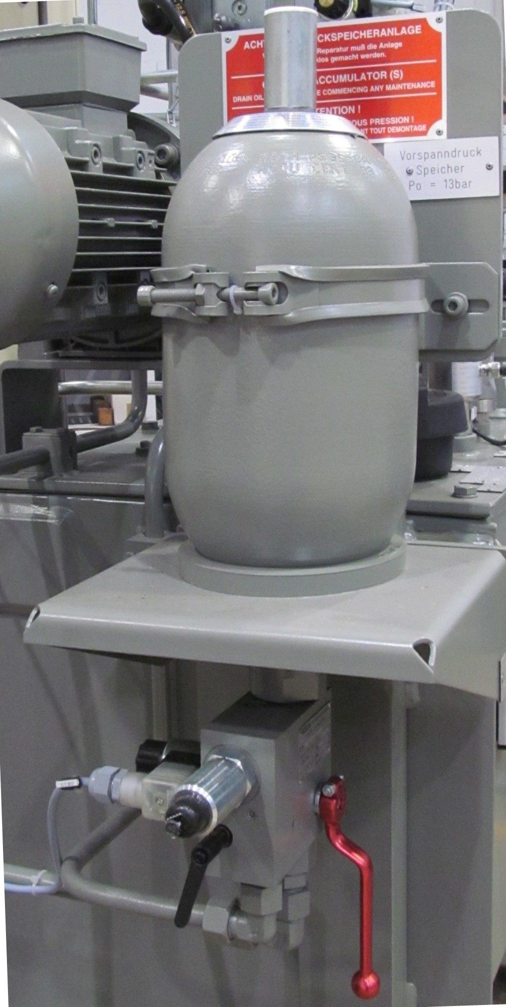
A hydraulic accumulator is a sealed cylinder or sphere divided by a floating piston, diaphragm or bladder. One side holds gas, nitrogen or air, at a set accumulator pre-charge; the other is connected to the system. As system pressure rises, fluid enters and compresses the gas, and the compressed gas pushes fluid back out when pressure falls. An accumulator:
- stores fluid under pressure and supplies the first flow when a service is selected;
- damps pressure fluctuations and absorbs thermal expansion;
- gives an emergency supply if the pumps fail;
- lengthens the time between cut-out and cut-in, reducing pump wear.
The pre-charge is set below normal system pressure but above the pressure any service needs, for example 1,500 psi in a 3,000 psi system. The stored volume is usually enough to operate a service once; brake accumulators are sized for a guaranteed number of applications. The 737's brake accumulator, charged by system B, can still give several brake applications or a parking brake application after both normal and alternate brake pressure are lost. Pre-charge can be checked or replenished only with system pressure released, so that the gas pushes the piston fully to the fluid end. A pre-charge that is too high or too low makes the cut-out valve cycle too often, with audible hammering.
Pump off-loading and cut-out valves
The automatic cut-out valve (ACOV) keeps a constant-delivery pump from working against a full system. Pump output passes through a non-return valve to charge the system and the accumulator. When system pressure reaches the set value, pressure under the ACOV piston lifts it and opens a poppet, and the pump output returns to the reservoir at low pressure: the pump has cut out. The non-return valve and accumulator hold system pressure. When a service is used and pressure falls, the poppet closes and the pump cuts in again.
ACOV periodicity, the time between cut-out and cut-in, is a health check. A long period shows a system that holds pressure; a short one shows a leak. An external leak shortens the period and lowers reservoir quantity; an internal leak, such as a failed actuator piston seal, shortens it with no fluid loss but a rising fluid temperature.
Hydraulic fire shut-off valves
A hydraulic fire shut-off valve, called the hydraulic fluid shutoff valve by Boeing, sits in the supply line from the reservoir to each engine-driven pump, so that fluid cannot feed an engine fire. On the A320 the green and yellow valves are upstream of their engine pumps and close when the crew push the ENG 1 or ENG 2 FIRE pushbutton; the ECAM HYD page shows an amber cross line when the valve is fully closed. Pulling a 737 engine fire switch closes the hydraulic fluid shutoff valve, with the fuel and bleed valves, and deactivates the pump's LOW PRESSURE light. On the E190-E2 the fire handle closes the fuel, hydraulic and bleed air shutoff valves, and the EDP shutoff valve also closes automatically if system 1 or 2 fluid exceeds 125 °C.
Pump cavitation
Cavitation occurs when the pressure at a pump inlet falls so low that vapour or air bubbles form in the fluid. The bubbles collapse violently when the pump compresses them, eroding metal surfaces, and the pump loses output; boiling in the suction line can also cause vapour lock, in which the pump cannot draw fluid at all. Low inlet pressure, especially at altitude, and hot fluid near its boiling point encourage it.
Pump cavitation is prevented mainly by pressurising the reservoir, so that the inlet always sees a positive pressure, and helped by fluids with a high boiling point such as phosphate esters. On the A320, if both engine 1 bleed and the crossbleed supply are lost, reservoir pressure drops, LO AIR PRESS appears in amber and the pumps may cavitate.
Exam tip: a constant-delivery pump needs an ACOV or relief valve to unload; a constant-pressure pump regulates itself. A PTU transfers power, not fluid. Short ACOV periodicity means a leak: external if quantity falls, internal if temperature rises.
Frequently asked questions
What is the difference between a constant-pressure and a constant-delivery hydraulic pump?
A constant-delivery, or fixed-volume, pump, typically a gear pump, delivers the same flow whatever the system needs, so an automatic cut-out valve or relief valve must return the surplus to the reservoir. A constant-pressure, or variable-volume, pump alters its own output to hold system pressure: more flow when services move, only a small lubricating flow when nothing moves. It wastes less energy and is standard on transport aircraft at 3,000 psi and above.
What does a power transfer unit (PTU) do?
A power transfer unit is a hydraulic motor driving a hydraulic pump. Pressure from one system turns the motor, and the pump pressurises another system, so power passes between systems but fluid does not, keeping them separate. On the A320 the PTU works in either direction between the green and yellow systems whenever their pressures differ by more than 500 psi. On the 737 it uses system A pressure to help system B.
When does the ram air turbine deploy on the A320?
The A320's RAT extends automatically if AC bus 1 and AC bus 2 are both lost with the aircraft above 100 kt, and the crew can extend it at any time with the RAT MAN ON pushbutton. It drives a pump that pressurises the blue hydraulic system at 2,500 psi instead of the normal 3,000 psi, and the blue system drives the emergency generator through a hydraulic motor. The RAT can be stowed only on the ground.
What is the purpose of the gas pre-charge in a hydraulic accumulator?
The pre-charge of nitrogen or air on one side of the accumulator's piston or diaphragm is what stores energy. Fluid pumped in compresses the gas, and the gas pushes the fluid back out when system pressure falls. The pre-charge is set below normal system pressure but above the pressure any service needs, for example 1,500 psi in a 3,000 psi system. It can be checked only with the system pressure released.
What is ACOV periodicity?
Periodicity is the time between successive cut-out and cut-in cycles of the automatic cut-out valve that off-loads a constant-delivery pump. A long period means the system holds pressure well. A short period means a leak: with an external leak the reservoir quantity also falls, while with an internal leak, such as a failed actuator seal, no fluid is lost but the fluid temperature rises.
What causes hydraulic pump cavitation?
Cavitation happens when the pressure at the pump inlet is so low that vapour or air bubbles form in the fluid. They collapse violently as the pump compresses them, eroding metal surfaces, and the pump loses output. It is prevented mainly by pressurising the reservoir so the inlet always sees a positive pressure, and helped by fluids with a high boiling point. On the A320, low reservoir air pressure is flagged because the pumps may cavitate.
Test yourself on Hydraulic Pumps and Power Sources
The v1prep banks cover this topic in Aircraft General Knowledge (021), with a worked explanation for every answer. EASA ATPL, PPL, IR and CPL, the FAA written tests and A320/B737 type ratings.
Start practising →Sources and further reading
- FAA Aviation Maintenance Technician Handbook, Airframe (FAA-H-8083-31), Hydraulic and Pneumatic Power Systems
- EASA Easy Access Rules for Aircrew (Part-FCL), theoretical knowledge syllabus, 021 Airframe, Systems, Electrics, Power Plant
- EASA Easy Access Rules for Large Aeroplanes (CS-25), CS 25.1435 Hydraulic systems
- 14 CFR 25.1435, Hydraulic systems
Library articles are written for study and exam preparation. They do not replace your aircraft's approved documentation, your operator's procedures or the regulations themselves.