Hydraulic System Principles and Fluids
An aircraft hydraulic system transmits power through a confined, almost incompressible liquid: a pump pressurises the fluid, pipes carry the pressure, and actuators turn it into force and movement. By Pascal's law the pressure acts equally throughout the fluid, so a small input can move large and distant loads.
Hydraulic systems move the heavy parts of an aeroplane: landing gear, flaps and slats, flight control surfaces, wheel brakes, nose wheel steering, thrust reversers and cargo doors. A pump in one place pressurises a liquid, pipes carry that pressure anywhere in the airframe, and an actuator at the far end turns it back into force and movement. A lever on the flight deck, or a flight control computer, only has to decide where the fluid goes.
The method gives high power, accurate control and rapid response for little weight. This article covers the physics, the fluids, and the parts that keep the fluid clean, cool and free of air. Pumps and accumulators are described in hydraulic pumps and power sources, and valves and jacks in hydraulic valves and actuators.
- Pascal's law and force multiplication
- Basic components and system layouts
- Mineral and phosphate ester fluids
- Reservoirs, stack pipes and pressurisation
- Filters and bypass indication
- Seals, O-rings and backing rings
- Fluid cooling and heat exchangers
- Foaming and hydraulic hammering
- What the flight crew sees
- Frequently asked questions
Pascal's law and force multiplication
Pascal's law states that pressure applied to a fluid in a confined space is transmitted undiminished and equally in all directions. Pressure is force per unit area, P = F/A. In aviation it is quoted in pounds per square inch (psi); EASA texts also use bar and meganewtons per square metre, 4,000 psi being about 276 bar or 27.6 MN/m² (1 bar is about 14.5 psi).
Because the pressure is the same everywhere in the fluid, the force it produces depends only on the area it acts on: F = P × A. This is hydraulic force multiplication. A force of 100 lb on a piston of 1 in² creates 100 psi, and the same 100 psi acting on a piston of 20 in² produces 2,000 lb. The gain is paid for in distance: to displace the fluid needed, the small piston must travel 20 times as far as the large one.
In an aircraft the pump holds one system pressure and each actuator is sized for its task: a large piston for gear retraction, a smaller one where less force is needed. A higher system pressure gives the same force from a smaller, lighter actuator, which is why large aircraft use high pressures.
| Aircraft | Typical normal system pressure |
|---|---|
| Light aircraft with a gear-type pump | About 1,500 psi |
| Most transport aircraft (A320, 737 NG, E190-E2) | 3,000 psi |
| Some transport aircraft | 4,000 psi |
| A380 and A350 | 5,000 psi |
The scheme relies on the liquid being practically incompressible. Even at 4,000 psi hydraulic fluid loses only about 1 % of its volume, whereas air would be squeezed to about 1 % of its original volume, so the fluid behaves almost like a solid rod and actuators respond at once. Pipeline friction rises with fluid velocity, pipe length, the number of bends and viscosity, so designers use generous bores, smooth pipes, gradual bends and the correct grade of fluid.
Exam tip: force equals pressure times area. At the same pressure, doubling the piston area doubles the force, and the piston then moves half as far for the same volume of fluid.
Basic components and system layouts
Every hydraulic system is built from the same six basic components:
- a reservoir, which stores fluid, feeds the pump and receives the return flow;
- a pump, driven by an engine, an electric motor, bleed air, a ram air turbine or by hand;
- a selector valve, which directs fluid to the chosen side of the chosen service;
- one or more jacks (actuators), which convert pressure into movement;
- a filter, which keeps the fluid clean;
- a relief valve, which returns fluid to the reservoir if pressure becomes excessive.
In an open-centre hydraulic system, when no service is selected the pump output flows continuously through the selector valves and back to the reservoir at low pressure; selecting a service diverts the flow to its actuator. The layout is simple and suits a constant-delivery pump on smaller aircraft, but the pump always circulates fluid and pressure is not instantly available.
In a closed-centre hydraulic system full system pressure is maintained at all times, either by a constant-pressure (variable-volume) pump or by an accumulator working with an automatic cut-out valve. Fluid flows only when a service is selected; when nothing moves, the pump reduces its output or is off-loaded. Because the pump works only when work is needed, this is the standard layout on transport aircraft.

Mineral and phosphate ester fluids
The ideal hydraulic fluid is relatively incompressible, lubricates pumps and seals, and keeps a suitable viscosity from about +80 °C to −70 °C. It needs a high boiling point against vapour lock and cavitation, a low freezing point and a flash point above 100 °C, and it should be non-flammable, chemically inert, non-corrosive and free from sludging and foaming. Two families are in service.
Mineral-based hydraulic fluid is refined petroleum oil. Its British specification is DTD 585 (DEF STAN 91-48); the US equivalent, the name used in FAA texts, is MIL-H-5606. It is dyed red and used with neoprene seals.
Phosphate ester hydraulic fluid, best known by the trade name Skydrol, is used in most modern transport aircraft. It is dyed purple (Type 500) or green (Type 700). Its advantages are fire resistance and a higher boiling point, which makes it less prone to vapour locking and pump cavitation. It needs butyl rubber seals, attacks paint, perspex, rubber and sealing compounds, and irritates skin and eyes, so spills are cleaned up at once and personal protection is worn.
| Mineral fluid | Phosphate ester fluid | |
|---|---|---|
| Specification or name | DTD 585, MIL-H-5606 | Skydrol |
| Colour | Red | Purple (Type 500), green (Type 700) |
| Seal material | Neoprene | Butyl |
| Fire resistant | No | Yes |
| Boiling point | Lower | Higher |
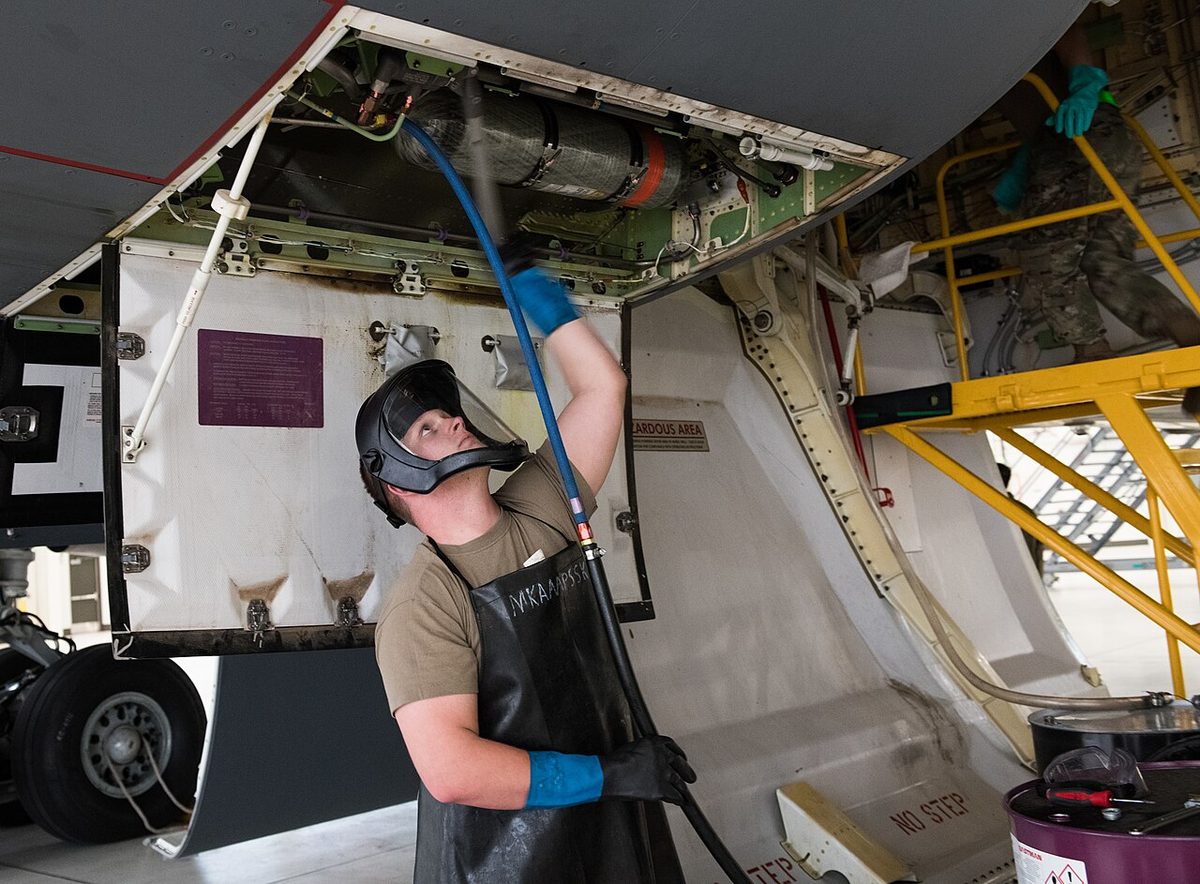
The two fluids must never be mixed. Each requires its own seal material, and the wrong fluid breaks the seals down, causing internal and external leakage and then component failure.
Warning: colour helps identify a fluid but is not proof. The approved specification comes from the aircraft maintenance manual, and fluid is taken only from sealed containers or an approved replenishment rig.
Reservoirs, stack pipes and pressurisation
The hydraulic reservoir stores the fluid, supplies the pump, receives the returning fluid and absorbs changes of volume. The level varies with the position of the jacks, because an extended jack holds more fluid than a retracted one, with the charge of the accumulators, and with temperature. On the Boeing 737, quantity indications vary normally after engine start, when the gear or leading edge devices move, and during cold soak in a long cruise. A reservoir usually carries a filler, a contents transmitter, a relief valve and sometimes a temperature probe.
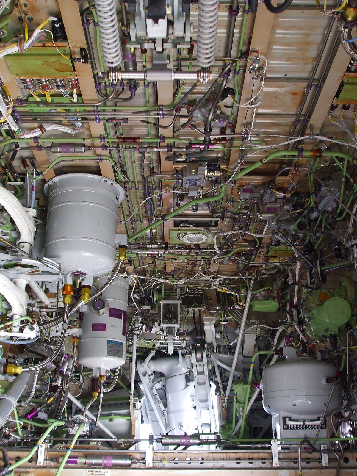
A stack pipe, or hydraulic reservoir standpipe, guards against total fluid loss. The main pump draws through a pipe standing above the reservoir floor, while the hand or emergency pump draws from the bottom. If a leak drains the main system down to the top of the stack pipe, the main pump loses suction but a reserve remains for essential services. On the 737 NG, a standpipe in the system A reservoir means that a leak in the engine-driven pump or its lines stops with the quantity at about 20 %, and the electric motor-driven pump keeps system A pressurised. A leak on the electric pump side, or in components common to both pumps, drains the reservoir to zero.
Hydraulic reservoir pressurisation keeps the fluid above ambient pressure. It gives the pump a positive inlet pressure, which prevents cavitation, and it stops dissolved air coming out of solution as bubbles at altitude, where the ambient pressure is low. The source is usually engine bleed air, on some types cabin pressurisation air, and a relief valve prevents overpressure. On the A320, HP bleed air from engine 1 pressurises the reservoirs automatically, with the crossbleed duct as a back-up; if the pressure falls, LO AIR PRESS appears in amber on the ECAM HYD page. The 737's system A and B reservoirs are pressurised by bleed air, and the standby reservoir is connected to the system B reservoir for pressurisation and servicing.
Filters and bypass indication
Cleanliness decides component life, so every system has several hydraulic filters:
- a suction filter at the pump inlet protects the pump;
- a high-pressure (HP) filter in the pressure line keeps every downstream component clean;
- a return line filter removes wear particles before the fluid re-enters the reservoir;
- a case drain filter in the drain line of a pump catches the debris that pump wear produces.
The A320 is typical: HP filters on each system, on the reservoir filling system and on the normal braking system, return line filters, and case drain filters on the engine-driven pumps and the blue electric pump, which maintenance inspects for metallic particles to monitor pump wear.
A filter clogging indicator, or differential pressure indicator, senses the pressure difference across the element. As the element loads with dirt the difference rises, and at a set value a button pops out or a warning lamp lights. Cold, thick fluid also causes a high difference across a clean element, so a bimetal device inhibits the indicator at low temperature to prevent false indications.
A filter bypass valve opens when the element is clogged beyond its design differential pressure, letting unfiltered fluid through so that the system keeps its flow and pressure. The price is dirty fluid circulating, so elements of this type are changed at scheduled intervals whatever the indicator shows.
Seals, O-rings and backing rings
A hydraulic seal is either static or dynamic. A static seal, such as a gasket or packing, is squeezed between two surfaces that do not move relative to each other, and seals reliably. A dynamic seal works between sliding surfaces, such as a piston in its cylinder; it needs lubrication, and slight seepage is normal.
The shape of a seal decides the direction in which it works. U-rings and V-rings seal in one direction only; the O-ring, of circular section, and square-section rings seal in both. At high pressure an O-ring can be forced into the gap between two moving surfaces and damaged. A backing ring (anti-extrusion ring) of stiff plastic or PTFE fitted beside it keeps its shape and prevents this extrusion. At the outer end of an actuator's gland, a wiper ring (scraper seal) scrapes dirt and grit off the piston rod as it retracts, so that they are not drawn into the seals, which matters most on landing gear actuators exposed to runway debris.
Fluid cooling and heat exchangers
Energy that a system does not deliver to a load ends up as heat in the fluid: an internal leak, such as a failed piston seal inside an actuator, raises the fluid temperature without any loss of quantity.
Transport aircraft cool the fluid in a hydraulic heat exchanger. On the Boeing 737, the fluid used to cool and lubricate the pumps passes through a heat exchanger in main fuel tank No. 1 (system A) or No. 2 (system B) before returning to the reservoir, and Boeing cautions that at least 760 kg of fuel must be in the related main tank before the electric motor-driven pumps are run on the ground. Temperature is monitored: on the A320, OVHT appears in amber on the ECAM HYD page when the fluid returning to a reservoir is too hot. The E190-E2 gives a HYD HI TEMP caution at 100 °C, takes the pump offline at 125 °C, and gives a HYD OVERHEAT warning at 145 °C.
Foaming and hydraulic hammering
Air in the fluid defeats the principle of the system, because air compresses where the liquid does not. Hydraulic fluid foaming happens when air comes out of solution, which low pressure encourages. Boeing notes that if the 737 system is not properly pressurised, foaming can occur at higher altitudes; it shows as pressure fluctuations and blinking pump LOW PRESSURE lights, and the MASTER CAUTION and HYD lights may come on momentarily.
Hydraulic hammering is the knocking, like water hammer, that pressure surges make as they run through the pipes. The accumulator normally damps such fluctuations. A classic cause is an accumulator with the wrong gas pre-charge, too high or too low: its storage capacity falls, the automatic cut-out valve cuts the pump in and out too often, and each cycle sends a surge through the system. The cure is to check and correct the pre-charge with the system off-loaded.
What the flight crew sees
The flight deck shows pressure and quantity for each system, often temperature, and warnings for low pressure, low quantity, overheat and pump failure. On the A320 ECAM HYD page system pressure is green and turns amber below 1,450 psi. The 737 shows a normal pressure of 3,000 psi, a maximum of 3,500 psi, and a white RF (refill) indication below 76 % quantity, valid on the ground with both engines shut down or after landing with flaps up.
Frequently asked questions
What is Pascal's law and why does it matter in aircraft hydraulics?
Pascal's law states that pressure applied to a fluid in a confined space is transmitted undiminished and equally in all directions. Because force equals pressure times area, the pressure made by a pump acts on every actuator in the system, and a larger piston gives a larger force from the same pressure. That lets one system pressure raise landing gear, move flight controls and apply brakes, with each actuator sized for its job.
What is the difference between Skydrol and mineral hydraulic fluid?
Mineral fluid, to DTD 585 in British usage or MIL-H-5606 in the United States, is refined petroleum oil, dyed red and used with neoprene seals. Skydrol is a phosphate ester, dyed purple (Type 500) or green (Type 700), used with butyl seals in most transport aircraft. Skydrol is fire resistant and has a higher boiling point, but it attacks paint, rubber and perspex. The two must never be mixed, because each destroys the other's seals.
Why are aircraft hydraulic reservoirs pressurised?
Pressurising the reservoir, usually with engine bleed air, keeps a positive pressure at the pump inlet so that the pump does not cavitate, and stops dissolved air coming out of solution as bubbles at altitude, where the ambient pressure is low. On the A320, HP bleed air from engine 1 pressurises the reservoirs, with the crossbleed duct as a back-up. Loss of reservoir air pressure is shown as LO AIR PRESS on the ECAM hydraulic page.
What is a stack pipe in a hydraulic reservoir?
A stack pipe, or standpipe, is a suction pipe that stands above the floor of the reservoir and feeds the main pump. An emergency or hand pump draws from the bottom of the reservoir. If a leak in the main system drains the fluid down to the top of the stack pipe, the main pump loses its supply but a reserve of fluid remains below it for the emergency pump to operate essential services.
What happens when a hydraulic filter becomes clogged?
As the element fills with dirt, the pressure difference across it rises. A differential pressure indicator then pops a button or lights a warning lamp; a bimetal device stops it giving false warnings when cold fluid is thick. If the difference keeps rising, a bypass valve opens and lets unfiltered fluid through, so the system keeps its flow and pressure. Because dirty fluid then circulates, such elements are changed at scheduled intervals.
What is the difference between an open-centre and a closed-centre hydraulic system?
In an open-centre system the pump output flows continuously through the selector valves back to the reservoir at low pressure when no service is selected, and is diverted to an actuator only when one is selected. In a closed-centre system full pressure is held at all times, by a variable-volume pump or an accumulator with a cut-out valve, and fluid flows only when a service moves. Most transport aircraft use closed-centre systems because they are more efficient.
Test yourself on Hydraulic System Principles and Fluids
The v1prep banks cover this topic in Aircraft General Knowledge (021), with a worked explanation for every answer. EASA ATPL, PPL, IR and CPL, the FAA written tests and A320/B737 type ratings.
Start practising →Sources and further reading
- FAA Aviation Maintenance Technician Handbook, Airframe (FAA-H-8083-31), Hydraulic and Pneumatic Power Systems
- EASA Easy Access Rules for Aircrew (Part-FCL), theoretical knowledge syllabus, 021 Airframe, Systems, Electrics, Power Plant
- EASA Easy Access Rules for Large Aeroplanes (CS-25), CS 25.1435 Hydraulic systems
- 14 CFR 25.1435, Hydraulic systems
Library articles are written for study and exam preparation. They do not replace your aircraft's approved documentation, your operator's procedures or the regulations themselves.