DC Generators, Motors and Starter-Generators
A DC generator converts mechanical rotation into direct current by turning an armature in a magnetic field and collecting its output through a commutator and brushes. Supplied with current instead, the same machine runs as a DC motor, and a starter-generator uses one machine for both jobs.
A DC generator turns engine power into direct current by rotating a set of coils, the armature, inside a magnetic field. It was the standard aircraft power source before the alternator replaced it, and it survives in two forms: on older light aircraft and, combined with a motor, as the starter-generator of turbine engines. The DC motor is the same machine run the other way, and it drives starters, actuators, pumps and fans throughout the aircraft.
Generators and motors share their construction, their principle (electromagnetic induction and the force on a current-carrying conductor) and their exam questions. The theory behind both is covered in electromagnetism and induction; this article deals with the machines, their protection and their indications.
DC generator construction
A DC generator has three main parts:
- the field system, stationary: pole pieces fixed inside the frame, each carrying a field winding (or permanent magnets) that sets up the magnetic field;
- the armature, rotating: coils of copper wire wound in slots of a laminated iron core on the shaft, driven by the engine;
- the commutator and brushes, which connect the rotating armature coils to the stationary external circuit.
As the armature turns, its conductors cut the magnetic flux and an EMF is induced in them; Fleming's right-hand rule gives the direction of the induced current. The EMF depends on the speed of rotation, the strength of the field and the number of armature conductors. Speed is set by the engine and the windings are fixed, so the only practical way to control the output is through the field.
That speed dependence is the generator's weakness. At idle or during a slow taxi its output may be too low to carry the load, and the battery discharges. The alternator, which gives useful output across the engine speed range and is lighter for its output, has therefore replaced the DC generator on most light aircraft.
| DC generator | Alternator | |
|---|---|---|
| Rotating part | Armature (output windings) | Field |
| Output taken through | Commutator and brushes, full current | Fixed stator terminals; only field current through slip rings |
| Low-rpm output | Poor | Useful across the rpm range |
| With a flat battery | Can excite itself from residual magnetism | Produces nothing: its field needs battery current |
| Reverse current protection | Cut-out or reverse current circuit breaker | Rectifier diodes block reverse current |
Armature, commutator and brushes
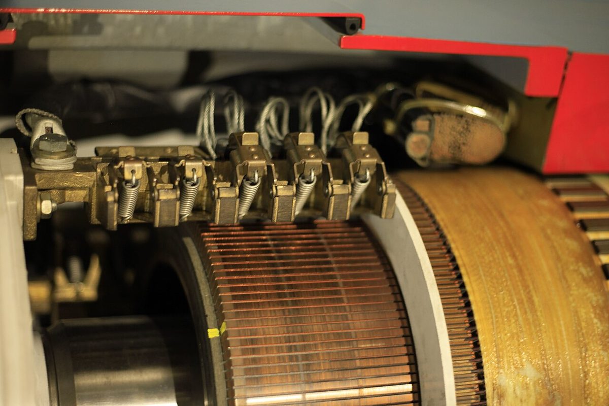
Each armature coil actually generates alternating EMF, because its sides pass north and south poles in turn. The commutator turns this into direct current. It is a ring of copper segments, insulated from one another, with each coil connected to a pair of segments. The segments swap from one brush to the other at the moment the coil's EMF reverses, so the output at the brushes always flows the same way. With many coils and segments the output is a nearly steady DC. The commutator is, in effect, a mechanical rectifier.
The carbon brushes are blocks of carbon, sometimes copper-graphite for heavier currents, pressed by springs against the turning commutator. They wear, shed carbon dust and need periodic inspection and replacement.
The whole output of the machine passes through this sliding contact, and that is the root of the DC generator's other drawbacks:
- wear and maintenance of brushes and commutator;
- arcing at the brushes, which gets worse in the low air pressure at altitude;
- radio interference from brush sparking, which is why commutator machines need screened cables (see electrical bonding, static and interference).
Field excitation and shunt winding
Field excitation is the current in the field windings that creates the magnetic field. A DC generator is normally self-excited: the field is fed from its own output. When it starts to turn, the small residual magnetism left in the pole pieces induces a small EMF, which drives a little current through the field, strengthening it, and the voltage builds up. This is why a DC generator can come on line with a dead battery, while an alternator, whose field must be fed from the battery, cannot.
Machines are classified by how the field winding is connected to the armature:
- Shunt-wound generator: the field winding is in parallel with the armature, across the output. The field current is small and largely independent of the load current. The voltage falls only slightly as the load increases, and with a voltage regulator the output is essentially constant, so this is the type used on aircraft.
- Series-wound: the field winding carries the full armature current.
- Compound-wound: both a series and a shunt field winding, the arrangement used in starter-generators.
The voltage regulator holds the output at its set value, about 14 V in a light aircraft system with a 12 V battery and about 28 V in a 28 V system with a 24 V battery. It senses the output voltage and adjusts the field current: less field current if the voltage is high (light load, high speed), more if it is low. The bus is deliberately held above battery voltage so that the battery charges.
Exam tip: the output voltage of an aircraft DC generator is regulated by varying the field current, and so the field strength. Speed and the number of turns are not controllable in flight.
Reverse current cut-out and overvoltage protection
Whenever the generator's voltage is below the battery's, at low rpm, during shutdown or after a failure, current would flow backwards from the battery into the armature. The battery would discharge itself rapidly, and the generator could be damaged. Two devices prevent this:
- The generator cut-out, or reverse current relay, is a relay whose contacts close, putting the generator on the bus, when its voltage rises above battery voltage. They open again as soon as current flows in the reverse direction.
- The reverse current circuit breaker (RCCB) does the same job on larger DC generator installations: it detects reversed current and disconnects the generator from the bus.
An alternator needs neither, because the diodes that rectify its output block reverse current.
The opposite failure is a runaway voltage regulator driving the output too high. The overvoltage protection unit monitors the generator voltage and, above a threshold such as about 16.5 V in a 14 V system or about 32 V in a 28 V system, opens the field circuit so that the output collapses. It protects the aircraft's equipment, and the pilot sees the generator drop off line. Checklists typically allow one reset of the generator or its field circuit breaker; if the output does not return, the crew sheds load and plans on battery endurance (see aircraft batteries).
Twin-engine aircraft have one generator per engine, connected through bus ties so that either can carry the essential load alone (see electrical power distribution).
Load ammeters and loadmeters
A load ammeter, or loadmeter, is connected in the generator's output lead. It shows the total current the generator is supplying to all the loads on the bus, including the battery's charging current. The load can only flow one way, so the scale starts at zero and reads only positive values. A low reading means a light electrical load; zero means the generator is not supplying anything.
The centre-zero ammeter is a different instrument, connected to the battery, and shows current into or out of it. A pilot must know which one is fitted, because the same generator failure looks different on each.
| Indication | Loadmeter | Centre-zero battery ammeter |
|---|---|---|
| Connected in | Generator output | Battery lead |
| Normal cruise | Positive, equal to the total load | Near zero or a small charge |
| Just after engine start | High, including battery recharge | Large charge, decreasing over a few minutes |
| Generator failed | Zero | Steady discharge, often with a low-voltage light |
On a light twin with one loadmeter per generator or alternator, the failed machine reads zero while the other picks up its share. The bus voltage hardly changes, so the loadmeters, not the voltmeter, show the failure.
Series- and shunt-wound DC motors
A DC motor converts electrical energy into mechanical energy. Current in the armature conductors, lying in the field, produces a force on each (Fleming's left-hand rule gives its direction), and the forces turn the armature. Its construction is essentially that of a DC generator, and a DC machine can often work as either.
As a motor turns, its armature also acts as a generator. The EMF induced in it, the back EMF, opposes the supply voltage and is proportional to speed. The armature current is set by the difference: current = (supply voltage − back EMF) / armature resistance. A motor therefore speeds up until its back EMF leaves just enough current to supply the torque the load demands.
| Series-wound motor | Shunt-wound motor | |
|---|---|---|
| Field connection | In series with the armature: same current through both | In parallel with the armature, across the supply |
| Starting torque | High, because the field strengthens with load current | Lower |
| Speed | Varies greatly with load; very fast on light load | Nearly constant, about 10 % variation from no load to full load |
| Hazard | Overspeed if the load is removed | Tolerates starting on light or no load |
| Aircraft uses | Engine starters, landing gear and flap actuators, hoists | Fans, centrifugal pumps, motor-generator units |
The series-wound motor suits loads that are heavy at the start and always connected. With no load, its current falls, the field weakens, and it must spin ever faster to generate enough back EMF, so it can overspeed and destroy itself. The shunt-wound motor, whose field is fixed by the supply voltage, runs at an almost constant speed whatever the load.
To reverse a DC motor, the current in either the field or the armature is reversed, but not both. Reversing the supply to a series motor reverses both at once, so it keeps turning the same way; its field connections must be reversed instead.
Inrush current and starting resistors
At the moment of starting the armature is stationary, so there is no back EMF, and only the small resistance of the armature winding limits the current. The result is an inrush current many times the running current, which can damage the windings and brushes or trip the circuit protection. It is also why an engine starter briefly draws hundreds of amperes from the battery.
A starting resistor, sometimes called a slow-start resistor, is connected in series with the armature to limit the inrush. As the motor accelerates and its back EMF builds up, the resistor is progressively shorted out, manually or automatically, until the motor runs directly on the supply.
Starter-generator operation
A starter-generator is a single compound-wound DC machine that does both jobs. For the start it runs as a compound motor and cranks the engine. Once the engine is self-sustaining, a changeover relay connects the shunt field to the voltage regulator, and the same machine becomes a DC generator supplying the bus. A typical rating quoted in exam texts is 300 A at 28 V.
The advantage is weight: one machine, one drive and one set of wiring instead of two. The drawback is that a machine designed for both roles cannot give its full output at low rpm. It therefore suits turbine engines, which run at high rpm throughout the flight, rather than piston engines. Most modern transport aircraft start their main engines with air turbine starters driven by bleed air instead (see gas turbine engine starting).
The idea of one machine for both jobs also appears on APUs, though not always as a DC machine. The Boeing 737 NG's APU generator is an AC generator, and it is also the APU's starter: it takes its starting power from the No. 1 AC transfer bus when AC power is available and from the aircraft's main battery otherwise. During a battery start the APU generator shows no frequency and zero volts on the AC meters until the start sequence is complete and the generator is ready to be connected. The start cycle, which may take up to 120 seconds, terminates automatically if the APU does not reach the proper speed and acceleration within the starter's time limit (see auxiliary power unit).
Frequently asked questions
What is the difference between a DC generator and an alternator?
A DC generator rotates its output windings, the armature, inside a stationary field and takes the whole output through a commutator and brushes. An alternator does the opposite: the field rotates and the output windings stay on the stator, and its AC is rectified by diodes where DC is needed. The alternator is lighter for its output, gives useful output at low rpm and needs less maintenance, but unlike a generator it cannot excite itself from residual magnetism.
Why does a DC generator need a reverse current cut-out?
When the generator's voltage falls below battery voltage, for example at low rpm or after a failure, current would flow backwards from the battery into the armature. The battery would discharge rapidly and the generator could be damaged. The cut-out, or reverse current relay, connects the generator to the bus only when its voltage exceeds the battery's and opens as soon as the current reverses. Alternators do not need one, because their rectifier diodes block reverse current.
Why must a series-wound motor never run without a load?
In a series-wound motor the same current flows through the field and the armature. With no load the current is small, so the field is weak and the motor must spin very fast before its back EMF balances the supply voltage. Its speed can rise until the motor is damaged. That is why series motors are used for loads that are always connected, such as engine starters and landing gear or flap actuators.
What is a starter-generator?
A starter-generator is a single compound-wound DC machine used on turbine engines. For the start it runs as a motor and turns the engine. Once the engine is self-sustaining, a changeover relay connects the shunt field to the voltage regulator and the machine becomes a generator supplying the bus. One machine instead of two saves weight, but it cannot give full output at low rpm, so it suits turbine engines rather than pistons.
What is the difference between a loadmeter and a centre-zero ammeter?
A loadmeter, or load ammeter, is connected in the generator or alternator output and shows the total current it supplies, including battery charging. It reads only positive values, and zero means the generator is off line. A centre-zero ammeter is connected to the battery and shows current into it on the charge side and out of it on the discharge side. A generator failure therefore shows as zero on a loadmeter and as a discharge on a centre-zero ammeter.
Test yourself on DC Generators, Motors and Starter-Generators
The v1prep banks cover this topic in Aircraft General Knowledge (021), with a worked explanation for every answer. EASA ATPL, PPL, IR and CPL, the FAA written tests and A320/B737 type ratings.
Start practising →Sources and further reading
- FAA Pilot's Handbook of Aeronautical Knowledge (FAA-H-8083-25), Chapter 7, Aircraft Systems (electrical system)
- FAA Aviation Maintenance Technician Handbooks, General (FAA-H-8083-30B) and Airframe (FAA-H-8083-31B), electricity, generators, motors and aircraft electrical systems
- FAA Aviation Maintenance Technician Handbook, Powerplant (FAA-H-8083-32B), engine starting systems and starter-generators
- EASA Easy Access Rules for Aircrew (Regulation (EU) No 1178/2011), ATPL and CPL theoretical knowledge learning objectives, subject 021
Library articles are written for study and exam preparation. They do not replace your aircraft's approved documentation, your operator's procedures or the regulations themselves.