Generator Control, Protection and Paralleling
Generator control is the regulation, protection and switching of each aircraft generator by its generator control unit (GCU). Paralleling is the connection of two or more AC generators to a common bus, which requires them first to be synchronised in voltage, frequency, phase and phase sequence.
Every AC generator on a transport aeroplane works under a generator control unit (GCU), a solid-state controller that regulates its voltage, watches it for faults and decides when it may be connected to its bus and when it must be taken off. Above the GCUs, a bus power control unit coordinates the network as a whole; see electrical power distribution.
Connecting generators in parallel adds two further tasks. Two AC machines can share a bus only when their voltage, frequency, phase and phase sequence agree, which is generator synchronisation, and once connected they must share the load evenly. Many modern types avoid both problems by never paralleling their AC sources: the Airbus A320 and the Boeing 737 NG work this way. The machines themselves are described in AC generators, CSD and IDG.
Generator control units
A GCU typically performs four functions:
- Voltage regulation, by varying the current in the field winding of the generator's exciter.
- Protection, against over- and under-voltage, over- and under-frequency, over- and under-excitation, differential current, reverse power and overcurrent.
- Switching, closing the generator's circuit breaker or line contactor when the machine is ready and tripping it on a fault.
- Synchronisation, in a paralleled system, before the generator is allowed onto the common bus.
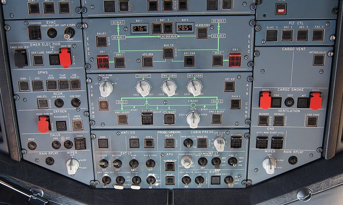
On the A320 each engine generator has its own GCU, which controls the frequency and voltage of the output and protects the network through the generator line contactor. On aircraft fitted with a ground and auxiliary power control unit (GAPCU), that unit regulates the APU generator's voltage and frequency through the APU electronic control box and controls both the external power contactor and the APU generator line contactor; aircraft without it have a ground power control unit (GPCU) for the external power contactor. The emergency generator has a GCU of its own, which keeps it at constant speed, controls its voltage and start-up and protects the network through its line contactor. It has no synchronising function, because the A320's generators are never paralleled. Each IDG of the first-generation Embraer E190 (E1) is likewise controlled by its own GCU.
In a variable speed constant frequency (VSCF) system the control and conversion electronics are combined in a generator converter control unit (GCCU), which turns the output of a frequency-wild generator into constant 115/200 V 400 Hz power.
Voltage regulation and field excitation
The output voltage of a generator depends on the strength of its magnetic field. The voltage regulator, part of the GCU in a modern aeroplane, senses the output voltage and adjusts the generator field excitation to hold it constant: more field current when the voltage sags, less when it rises. In this way it compensates for changes of electrical load and of speed. In a brushless machine the regulator acts on the exciter's field, and the exciter in turn supplies the main field. On the Boeing 737 the voltage regulator controls generator output voltage automatically, and the frequency meter reads only while the generator is excited.
Removing the excitation is also how a generator is switched off electrically. On the A320, the GEN pushbutton in its normal position energises the generator field, and the line contactor closes if the electrical parameters are normal. Selected OFF, it de-energises the field, opens the line contactor and resets the fault circuit, without affecting the IDG. The control unit can remove the excitation in the same way when a fault calls for the generator to be shut down. The same principle protects DC generators, whose overvoltage unit opens the field circuit if a failed regulator lets the voltage run away (see DC generators, motors and starter-generators).
The flight deck shows the result. On the A320's ECAM ELEC page, generator voltage turns amber below 110 V or above 120 V, frequency below 390 Hz or above 410 Hz, and load above 100 % of rated output. These are indication thresholds, not the GCU's trip values.
Generator and line contactors
Between each generator and its bus sits a heavy-duty contactor, called the generator circuit breaker (GCB) by Boeing and in the ATPL syllabus, and the generator line contactor (GLC) by Airbus. It closes when the generator is on line and ready and opens on a fault, isolating the failed machine while the rest of the system keeps running. On the 737 the GEN switch closes the generator circuit breaker, after disconnecting the previous source from the transfer bus, and opens it when selected OFF; a blue GEN OFF BUS light shows that the IDG is not supplying its transfer bus. On the A320 the GEN FAULT light comes on if the GCU trips the generator or the line contactor opens, except when the pushbutton has been selected OFF.
Other sources have their own line contactor: external power, the APU generator and the emergency generator each connect to the network through one. On the A320 the APU generator line contactor closes only if the generator's parameters are normal and the external power contactor is open, because with the EXT PWR pushbutton on, external power takes priority over the APU generator; the engine generators take priority over both.
A line contactor can be opened while its generator keeps running. In the A320 smoke drill, selecting the GEN 1 LINE pushbutton OFF opens the GEN 1 line contactor, and AC BUS 1 is then supplied by GEN 2 through the bus tie contactors. If the drill goes on to the smoke configuration, the main busbars are shed as in the emergency configuration, except that the fuel pumps are connected upstream of the open GEN 1 line contactor and so stay supplied by GEN 1.
Protection against faults
Each protection trips the generator off line by opening its breaker and, where needed, removing its excitation:
| Protection | What it guards against |
|---|---|
| Over- and under-voltage | Output voltage out of limits, for example after a regulator failure |
| Over- and under-frequency | Output frequency out of limits, which points to the speed of the drive |
| Over- and under-excitation | Field current out of limits |
| Differential current | A short circuit, or an open phase, between the generator and its bus |
| Reverse power | In a paralleled system, a generator absorbing power instead of supplying it |
| Overcurrent | Load current above the generator's capability |
Differential current protection uses current transformers at both ends of the protected zone, at the generator and at the bus. By Kirchhoff's current law the current entering the zone must equal the current leaving it. A short circuit to structure inside the zone diverts part of the current into the fault, the two readings disagree, and the GCU trips the generator circuit breaker. Because such a fault may still be present, resets are limited: on the A320, after a differential fault has tripped a generator, the reset has no effect after two attempts.
Reverse power protection belongs to paralleled systems. If a generator's drive fails while it is connected to the common bus, the other generators keep it turning as a motor, drawing power from the system; the protection detects the reversed flow of power and trips it. DC systems meet the same problem as reverse current, which a reverse current cut-out prevents.
Exam tip: Differential protection compares the current at the two ends of a feeder; a difference means current is leaking into a fault between them. It trips the generator circuit breaker, as do the voltage, frequency and excitation protections.
Synchronising generators
Before an AC generator can be connected to a bus already fed by another, four conditions must be met:
- Voltage. Equal voltages; a mismatch drives a heavy circulating current between the machines.
- Frequency. Equal frequencies; otherwise the machines drift in and out of step, producing a beat.
- Phase. The two waveforms at the same point in their cycle at the moment of closing; otherwise the machines are wrenched into step with a severe current surge.
- Phase sequence. The same order of phases; with a reversed sequence the machines can never come into step, and three-phase motors would run backwards. For the same reason, external power with an incorrect phase sequence is rejected by the aircraft.
In an automatic system a synchronising unit, or the GCU itself, checks all four and holds the breaker open until they agree. The Embraer E190-E2 uses the idea briefly: when AC sources are changed, its no break power transfer function connects the outgoing and incoming sources in parallel for a few milliseconds, so that the transfer happens without a power break, and then separates them. The Boeing 737 NG does the opposite: connecting a source to a transfer bus automatically disconnects the source already there, so the two are never connected together, even briefly.
The dark lamp method
The dark lamp method is the classic manual way of synchronising. A lamp is connected between each phase of the incoming generator and the matching phase of the running bus, so that each lamp sees the difference between the two voltages. If the frequencies differ slightly, the lamps brighten and dim together in a slow beat; the slower the beat, the closer the frequencies. When the voltages are equal and in phase, the difference is zero and all three lamps are dark. The breaker is closed in the middle of a dark period.
The lamps also check phase sequence: if they go dark one after another instead of together, the sequence is wrong and the machines must not be connected. On modern aeroplanes synchronisation is automatic, but the principle remains an examination topic.
Load sharing and the synchronising bus
In a paralleled AC system each generator feeds its own bus and, through a bus tie breaker (BTB), a common synchronising bus (tie bus). All the generators then share the total load, with the GCUs controlling load sharing so that each carries an equal part. The benefit is redundancy: if one generator fails, the others carry its share without any bus losing power. The cost is the complexity of synchronising and load-sharing control. Because paralleled machines are locked to one common frequency, their share of the real load (kW) is balanced by trimming the speed of each drive, and their share of the reactive load (kVAR) by trimming each machine's excitation.
A split bus system sidesteps the problem. Each generator feeds its own bus, the bus ties are normally open, and after a generator failure they close so that a single healthy source supplies both buses. The A320's generators cannot be connected in parallel; its bus tie contactors open and close automatically so that separate sources share the load between them. The 737 follows the same principle: its AC sources are never paralleled.
Paralleling is simpler with DC. In a typical light twin the two alternators operate in parallel through their voltage regulators and share the load. When one fails the bus voltage hardly changes, so the reliable sign is a zero reading on that alternator's ammeter, with a corresponding rise on the other.
Frequently asked questions
What does a generator control unit do on an aircraft?
A generator control unit (GCU) looks after one generator. It regulates the output voltage by varying the field excitation, protects against faults such as over- and under-voltage, over- and under-frequency, differential current and, in paralleled systems, reverse power, and opens or closes the generator's line contactor. In a paralleled system it also checks synchronisation before the generator joins the common bus. On the A320 each GCU also controls its generator's frequency.
What conditions must be met before two AC generators are paralleled?
Their voltage, frequency, phase and phase sequence must all match. A voltage difference drives a heavy circulating current between the machines, a frequency difference makes them drift in and out of step, closing out of phase causes a severe current surge, and with the wrong phase sequence they can never come into step at all. A synchronising unit or the control unit holds the breaker open until all four conditions are met.
How does the dark lamp method of synchronising work?
Lamps are connected between the matching phases of the incoming generator and the running bus, so each lamp sees the difference between the two voltages. When the frequencies differ slightly the lamps brighten and dim together in a slow beat; the slower the beat, the closer the frequencies. The breaker is closed in the middle of a dark period, when the machines are in phase. Lamps going dark in turn rather than together show a wrong phase sequence.
What is differential protection on an aircraft generator?
Differential protection compares the current leaving the generator with the current arriving at its bus, using current transformers at each end of the protected zone. Normally the two are equal. A short circuit inside the zone diverts some current to the fault, the two readings disagree, and the control unit trips the generator off line. On the A320, a generator tripped by a differential fault cannot be reset after two attempts.
Why are the A320's generators never paralleled?
The A320, like the Boeing 737 NG, uses a split system: each generator feeds its own AC bus, and bus tie contactors open and close automatically so that a single healthy source can take over a bus whose generator has failed. Because no two AC sources ever run together, no synchronising or load-sharing control is needed, which makes the system simpler. The APU generator and external power are connected in the same way.
Test yourself on Generator Control, Protection and Paralleling
The v1prep banks cover this topic in Aircraft General Knowledge (021), with a worked explanation for every answer. EASA ATPL, PPL, IR and CPL, the FAA written tests and A320/B737 type ratings.
Start practising →Sources and further reading
Library articles are written for study and exam preparation. They do not replace your aircraft's approved documentation, your operator's procedures or the regulations themselves.