Electrical Power Distribution
Electrical power distribution is the network of busbars, contactors, relays and circuit protection that carries power from the generators, batteries and external supplies to every load in the aircraft, and that reconfigures itself after a failure so that the loads essential to safe flight stay powered.
Generating electrical power is only half the task; it must also reach hundreds of loads, and keep reaching the important ones when something fails. The distribution system does this with busbars that collect power from the sources, contactors and relays that connect and disconnect sources and buses, circuit breakers that protect each branch, and control logic that reconfigures the network automatically after a failure.
A light single has one bus and a master switch; a transport aeroplane has a dozen or more buses in a hierarchy, from main buses down to essential and battery buses that stay powered when all the generators have gone. This article covers the layouts and terms; generation is covered in AC generators, CSD and IDG and generator control, protection and paralleling, and the batteries in aircraft batteries.
Busbars and system architecture
A busbar, or bus bar, is a heavy copper conductor, a strip, rod or thick cable, that acts as a distribution centre. Generators, the battery and external power feed it, and each load takes its supply from it through its own circuit breaker and switch. The loads are therefore connected in parallel: each receives full bus voltage, and the failure of one does not affect the others. An electrical bus is any such distribution point.
The main bus is the primary distribution point, fed directly by a generator and, as back-up, the battery; the major loads and the lesser buses take their supply from it. Multi-engine aircraft split the main bus into several, each normally fed by its own generator, for redundancy. Below them come the essential buses, the battery buses and the hot battery bus, which is connected directly to the battery with no switch at all.
Transport aeroplanes generate three-phase AC at 115/200 V and 400 Hz and obtain their DC from it through transformer rectifier units (TRUs); light aircraft generate DC directly. Both use one of two DC standards: a 14 V system with a 12 V battery in many light aircraft, or a 28 V DC power system with a 24 V battery in larger aircraft, the bus being held above battery voltage so that the battery charges. TRUs are described in transformers, converters and AC motors.
The whole network is the electrical system, abbreviated ELEC: the A320's ECAM has an ELEC page showing sources, contactors and buses, and the Boeing 737's amber ELEC light shows, on the ground, a fault in the DC or standby power system.
Single-pole and two-pole wiring
Most metal aircraft use a unipole, or single-pole, earth-return system. The negative sides of the generators, the battery and every load are connected to the airframe, which forms the return path, so only the positive wire runs from the bus to each load. This saves a great deal of wire weight, but it depends on good electrical bonding between all parts of the structure (see electrical bonding, static and interference).
A dipole, or two-wire, electrical system runs both a positive and a negative wire to each load. It is needed where the structure does not conduct, as in composite or fabric airframes, and is heavier. Modern composite aircraft use dipole or hybrid systems with dedicated metal return paths.
Split and paralleled bus systems
Two basic layouts are used for the AC generators of multi-engine aircraft.
In a split bus system each generator feeds its own main AC bus, and the generators are never connected in parallel. The bus tie between them is normally open. When a generator fails, the tie closes automatically and the remaining source feeds both buses, with no crew action needed; the crew can then bring the APU generator on line to restore independent supplies. Because no two AC sources ever run together, no synchronising or load sharing control is needed, and a fault on one side cannot be fed by both generators at once. The Airbus A320 and the Boeing 737 are split systems; on the 737 there is no paralleling of AC sources, and connecting a source to a transfer bus automatically disconnects the source already on it.
In a paralleled AC system each generator is connected through its bus tie breaker (BTB) to a common synchronising bus, or tie bus, and all share the total load, their generator control units balancing the shares. If one generator fails, the others carry its load without any bus losing power. The cost is complexity: every generator must match the others in voltage, frequency, phase and phase sequence before its breaker closes. Paralleled systems are typical of the Boeing 747 and other classic transports; synchronising and load sharing are described in generator control, protection and paralleling.
| Split bus system | Paralleled system | |
|---|---|---|
| Generators connected together | Never | Always, via the synchronising bus |
| Bus ties in normal operation | Open | Closed |
| After a generator failure | Tie closes, one source feeds both buses | Remaining generators carry the load, no transfer |
| Synchronising and load sharing | Not needed | Needed |
| Examples | A320, Boeing 737 | Boeing 747 and other classic transports |
Bus ties and the BPCU
A bus tie is a switchable connection between two main buses. It is made by a heavy-duty contactor, called a bus tie breaker (BTB) or bus tie contactor (BTC) depending on the manufacturer, and it is normally operated automatically.
On the A320 the BUS TIE pushbutton is normally left at AUTO, and the two bus tie contactors open and close to keep AC BUS 1 and AC BUS 2 powered. Both close when a single source, one engine generator, the APU generator or external power, must supply the whole network; only one closes when an engine generator supplies its own side and the APU generator or external power supplies the other.
On the Boeing 737 the BUS TRANSFER switch, guarded at AUTO, lets the BTBs operate automatically so that if the source on one transfer bus fails, the source on the other picks up the unpowered bus. Selecting it OFF keeps the two transfer buses isolated and opens the DC cross tie relay to separate DC bus 1 from DC bus 2.
Each generator has its own generator control unit (GCU), which regulates and protects it. Above them, larger aircraft have a bus power control unit (BPCU), a central system manager. It monitors the generators and buses through current transformers and voltage sensing, coordinates the generator and bus tie breakers across the system, detects a faulty generator or bus, and reconfigures the distribution automatically to keep as much of the network powered as possible.
Main and essential buses
The essential bus carries the loads needed for continued safe flight and landing: essential flight instruments, communication and navigation, and essential lighting. It is fed from a main bus in normal operation, but it is designed to stay powered after the main generation fails. Loads that can be lost, such as galleys, cabin lighting and entertainment, are kept on non-essential buses so that they can be shed. Dividing loads between an essential bus bar and a non-essential bus bar adds no generating capacity; its purpose is to allow the non-essential loads to be shed in a single action.
The A320 shows the hierarchy in full. Its AC buses are AC BUS 1 and 2, the AC ESS BUS, the AC SHED ESS BUS and the AC STAT INV BUS; its DC buses are DC BUS 1 and 2, the DC BAT BUS, the DC ESS BUS, the DC SHED ESS BUS, the DC entertainment bus and two HOT BUSes. AC BUS 1 normally feeds the AC ESS BUS; if AC BUS 1 is lost, the AC ESS FEED pushbutton transfers it to AC BUS 2, automatically on aircraft fitted with auto switching. An essential TR can supply the DC ESS BUS from the AC ESS BUS when the normal TRs are unavailable.
The 737 divides its system into AC power, DC power and standby power. Each side's AC system has a transfer bus, a main bus, two galley buses and a ground service bus.
External and ground power
On the ground the aircraft can be powered without running its engines or APU, and without draining its battery, from a ground power unit (GPU) or a fixed ground supply. The supply plugs into an external power receptacle: on both the A320 and the 737 it is near the nose landing gear, on the 737 on the lower right side of the fuselage. Large aircraft take three-phase 115/200 V 400 Hz AC; some smaller types take 28 V DC.
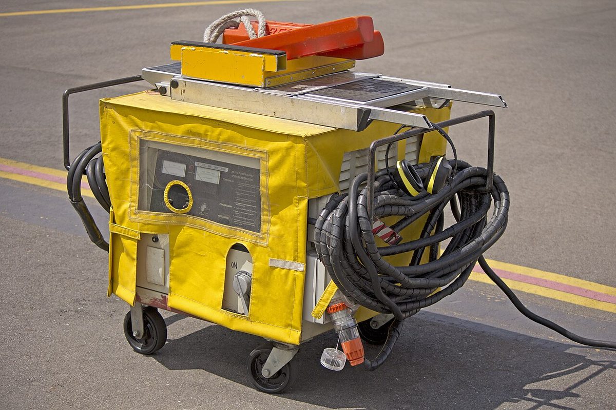
External power is protected automatically. The external power contactor will not connect the ground supply to buses already supplied by the aircraft's own generators, since the two are not synchronised; a supply with an incorrect phase sequence, which would run motors backwards, is rejected; and the supply is shut off if its voltage is too high. On the 737 a blue GRD POWER AVAILABLE light shows that ground power is connected and meets the aircraft's power quality standards.
Priorities between sources are fixed by the logic. On the A320 the engine generators have priority over external power, and external power, when its pushbutton is ON, over the APU generator. On the 737, when both external power and the APU are available, whichever is selected last powers both transfer buses; one cannot power one side and the APU the other. For servicing, part of the network can be powered alone: the 737's GROUND SERVICE switch connects external power to the ground service buses without powering the transfer buses, and the A320's MAINT BUS switch lets external power supply only the AC and DC GND/FLT buses.
Standby power and changeover relays
When the main generators fail, the essential loads are transferred to standby electrical power: an emergency generator, a static inverter and the batteries. The transfer is made by relays.
- The changeover relay of the essential AC bus normally connects it to a main AC bus; after a dual generator failure it switches the bus automatically to the emergency static inverter, driven by the battery.
- The DC isolation relay normally connects the essential and non-essential DC buses, both fed by the TRUs; after a dual generator failure it opens, so that the battery feeds only the essential DC bus and its limited capacity is not spent on non-essential loads.
On the Boeing 737, with the STANDBY POWER switch at AUTO and all AC power lost, the battery powers the AC standby bus through the static inverter and the DC standby bus and battery bus directly. Two fully charged batteries provide standby power for at least 60 minutes. On the A320, loss of both main AC buses above 100 kt extends the ram air turbine, which, through the blue hydraulic system, drives an emergency generator supplying the essential and shed-essential buses; until it comes on line, or if it is unavailable, the batteries and the static inverter take over and the shed-essential buses are shed. On the ground on batteries alone, the AC ESS BUS itself is shed below 50 kt, which removes all the display units.
Examination texts require a battery to carry the essential loads for at least 30 minutes after a total generator failure; the actual time depends on the battery and the load, and the aircraft flight manual governs.
Load shedding
Electrical load shedding is the disconnection of non-essential loads when the available generating capacity falls, so that the remaining sources can carry the essential ones. On transport aircraft it is automatic and follows sensed load or the loss of a source.
- On the A320, losing one generator in flight sheds the main galley, the in-seat power supply and the in-flight entertainment (IFE) system; with the galley automatic shedding feature the secondary galley is shed too. The DC entertainment bus needs two generators in flight.
- On the Boeing 737, a single generator sheds load in steps as overload is sensed: first the galleys and main bus on AC transfer bus 2, then those on transfer bus 1, then the IFE buses. In flight with the APU as the only source, all galley and main buses are shed automatically. The crew can try to restore galley and main bus power by cycling the CAB/UTIL switch off and on, and can remove power from the cabin and entertainment systems with the CAB/UTIL and IFE/PASS SEAT switches.
- The A320 smoke procedure uses the same mechanism for a different purpose: to isolate a possible source of smoke, the main busbars are shed, removing about 75 % of the electrical equipment.
In a light aircraft, shedding is the pilot's job. A steady discharge on the centre-zero ammeter with a low-voltage warning means the alternator has failed and the battery is carrying everything; the pilot turns off non-essential equipment, keeps the transponder and one radio, and lands while battery power remains.
Exam tip: load shedding exists to protect the essential loads. Galleys, cabin systems and entertainment go first; the essential buses are the last thing the system gives up.
Frequently asked questions
What is a bus tie on an aircraft?
A bus tie is a switchable connection between two main buses, made by a bus tie breaker or bus tie contactor. In a split system it is normally open, each generator feeding its own bus, and it closes automatically when a generator fails so that the remaining source supplies both buses. In a paralleled system the bus tie breakers are normally closed, connecting every generator to a common synchronising bus so that they share the load.
What is the difference between a split bus and a paralleled system?
In a split bus system each generator feeds its own main bus and the generators are never connected together; a bus tie closes only when one source must feed both sides. No synchronising or load sharing is needed, and a fault on one side cannot be fed by both generators. The A320 and Boeing 737 are split. In a paralleled system all generators feed a common synchronising bus and share the load, which needs synchronisation before each one is connected.
What is an essential bus?
An essential bus carries the loads needed for continued safe flight and landing, such as essential flight instruments, communication and navigation equipment and essential lighting. It is normally fed from a main bus, but it is designed to stay powered when the main generation fails, from an emergency generator, a static inverter or the battery. Non-essential loads such as galleys, cabin systems and in-flight entertainment are kept on other buses so they can be shed.
What is load shedding on an aircraft?
Load shedding is the disconnection of non-essential electrical loads when the available generating capacity falls, so that the remaining sources can carry the essential ones. It is usually automatic. On the A320, losing one generator in flight sheds the main galley, in-seat power and in-flight entertainment. On the Boeing 737, an overloaded single generator sheds the galleys and main buses one side at a time, then the entertainment buses. In a light aircraft the pilot sheds loads manually.
Why can external power not be connected while the aircraft's generators are running?
An external supply is not synchronised with the aircraft's generators, so connecting the two in parallel could cause large circulating currents and damage. The external power circuit therefore prevents a ground supply from connecting to buses already supplied by the aircraft's own generators. It also rejects a supply with the wrong phase sequence, which would run motors backwards, and the supply is shut off if its voltage is too high.
What is a hot battery bus?
A hot battery bus is connected directly to the battery with no switch in the circuit, so it stays powered even when the battery switch is off and the aircraft is otherwise dead. It supplies small loads that must always have power, such as fire detection, clocks, emergency exit lights and memory backup. On the Boeing 737 a separate switched hot battery bus is powered whenever the battery switch is on.
Test yourself on Electrical Power Distribution
The v1prep banks cover this topic in Aircraft General Knowledge (021), with a worked explanation for every answer. EASA ATPL, PPL, IR and CPL, the FAA written tests and A320/B737 type ratings.
Start practising →Sources and further reading
- FAA Aviation Maintenance Technician Handbook, Airframe (FAA-H-8083-31B), Aircraft Electrical System
- FAA Pilot's Handbook of Aeronautical Knowledge (FAA-H-8083-25C), Chapter 7, Aircraft Systems
- EASA Easy Access Rules for Large Aeroplanes (CS-25), CS 25.1351 to 25.1365, electrical systems and equipment
- 14 CFR 25.1351, Electrical Systems and Equipment, General
- EASA Easy Access Rules for Aircrew (Regulation (EU) No 1178/2011), ATPL and CPL theoretical knowledge learning objectives, subject 021
Library articles are written for study and exam preparation. They do not replace your aircraft's approved documentation, your operator's procedures or the regulations themselves.