B737 Bleed Air and Anti-Ice
The Boeing 737 bleed air system takes compressed air from the engines, the APU or a ground cart into a duct split in two by an isolation valve, and supplies it to the air conditioning packs, engine starting, the thermal anti-ice of the engine cowls and inboard slats, and the pressurisation of the hydraulic reservoirs and potable water tank.
The Boeing 737's bleed air system takes hot compressed air from the engines or the APU and distributes it through one duct, divided into a left and a right half by an isolation valve. Bleed air pressurises and air-conditions the cabin, starts the engines, keeps the engine intakes and part of the wing leading edges free of ice, and pressurises the hydraulic reservoirs and the potable water tank.
On the flight deck the crew see little of this: a few BLEED switches, the isolation valve switch, a duct pressure gauge and amber lights for trips and overheats. Exam questions focus on the logic behind those controls, above all when the isolation valve opens, what DUAL BLEED forbids and what a WING-BODY OVERHEAT light covers. This article follows the 737 Next Generation (NG) FCOM and notes where the 737 MAX differs. The general principles are in bleed air and pneumatic systems and thermal anti-icing.
Bleed air system overview
The bleed air system has three possible sources: the two engines, the APU, and an external air cart, which can supply air for engine start or air conditioning on the ground. Its users are:
- air conditioning and pressurisation (see B737 air conditioning);
- wing and engine thermal anti-icing;
- engine starting;
- hydraulic reservoir and potable water tank pressurisation;
- on certain variants, the aspirated TAT probe and the nitrogen generation system.
On the NG's CFM56-7B engines, bleed air is taken from the 5th and 9th compressor stages. During take-off, climb and most of the cruise, low-pressure air from the 5th stage is enough and the high stage valve stays closed; when 5th-stage air is insufficient, the high stage valve modulates open to keep the pressure up. Downstream, the engine bleed air valve acts as a pressure regulator and shutoff valve. With its BLEED switch ON it is DC activated and pressure operated, so it needs bleed pressure to open.

The APU bleed air valve is also DC controlled and pressure operated, and it closes automatically when the APU shuts down. The APU can supply both packs on the ground but only one in flight. The APU is run for two full minutes before it is used as a bleed air source, and the APU switch at OFF closes the APU bleed valve while the APU runs on for a 60-second cooling period. The APU's own limits, including the altitude limits for bleed air use, are in B737 APU.
For engine start, the ENGINE START switch in GRD uses battery power to close that engine's bleed air valve and open its start valve, so the starter receives air from the APU, a ground cart or the other engine. At starter cutout, about 56 % N2, the switch returns to OFF and the bleed valve goes back to the position selected.
Isolation valve and duct pressure
The isolation valve separates the left and right sides of the bleed duct during normal operation. It is AC operated. With the ISOLATION VALVE switch in AUTO:
- the valve is closed when both engine BLEED switches are ON and both PACK switches are in AUTO or HIGH;
- it opens automatically if either engine BLEED switch or either PACK switch is set OFF.
The APU BLEED switch does not affect the valve. Normally, then, engine 1 supplies the left pack and engine 2 the right pack, each through its own half of the duct. Switching off one engine bleed or one pack opens the isolation valve, so that the remaining source can reach both sides or the remaining pack can draw from either engine.
Exam tip: in AUTO the isolation valve responds to the positions of the two engine BLEED switches and the two PACK switches only. The APU BLEED switch plays no part in it.
The bleed air duct pressure indicator shows the pressure in the left (L) and right (R) sides of the duct. It is AC operated. A difference between L and R is considered normal as long as there is enough air to pressurise the cabin.
Bleed trip off and trip reset
Bleed trip off is the protection of each engine bleed system against excessive temperature or pressure. When either occurs, the related engine bleed air valve closes automatically and the amber BLEED TRIP OFF light comes on. The light, and the closed valve, require a reset: once the fault has cleared, pushing the TRIP RESET switch reopens the valve and extinguishes the light. The same switch resets the PACK and ZONE TEMP lights of the air conditioning system, but only if the fault condition is corrected.
The BLEED TRIP OFF lights remain powered on the batteries alone, together with the pack valves and PACK lights. Losing one side need not cost the cabin its pressure: a single pack in high flow can maintain pressurisation and acceptable temperatures up to the maximum certified ceiling.
Dual bleed
The amber DUAL BLEED light warns that the APU and an engine can both feed the duct. It comes on when the APU bleed air valve is open and:
- the engine No. 1 BLEED switch is ON; or
- the engine No. 2 BLEED switch is ON and the isolation valve is open.
The logic reflects the layout: the APU duct joins the left side, so engine No. 1 always meets APU air, while engine No. 2 meets it only through the open isolation valve. With both sources open, the FCOM notes that at idle thrust APU air can back-pressure the engine's 9th-stage modulating and shutoff valve, and the limitations protect the APU from engine bleed backflow at higher power. Thrust must therefore be limited to idle while DUAL BLEED is lit, and during an engine start with the APU bleed valve open, engine power above idle is avoided. With ground air connected and the isolation valve open, the APU bleed valve must be closed.
In the preflight configuration (ISOLATION VALVE OPEN, engine and APU BLEED switches ON) the DUAL BLEED light is expected to be on. After engine start the before taxi procedure sets the PACK switches to AUTO, the isolation valve to AUTO and the APU BLEED switch OFF, which extinguishes it.
Wing-body overheat
A wing-body overheat is caused by a leak from a bleed air duct and is sensed by overheat sensors. The amber WING-BODY OVERHEAT lights show which side:
| Light | Areas covered |
|---|---|
| Left | Left engine strut, left inboard wing leading edge, left air conditioning bay, keel beam, APU bleed air duct |
| Right | Right engine strut, right inboard wing leading edge, right air conditioning bay |
The keel beam and the APU bleed duct are covered by the left light only. Pushing the wing-body OVHT TEST switch checks the detector circuits: both WING-BODY OVERHEAT lights, both MASTER CAUTION lights and the AIR COND annunciator come on. Leak detection on other types is compared in fire and overheat detection.
Pulling an engine fire switch also closes that engine's bleed air valve, which removes wing anti-ice from the affected wing and closes the bleed-air-operated pack valve (see B737 fire protection).
Engine cowl anti-ice
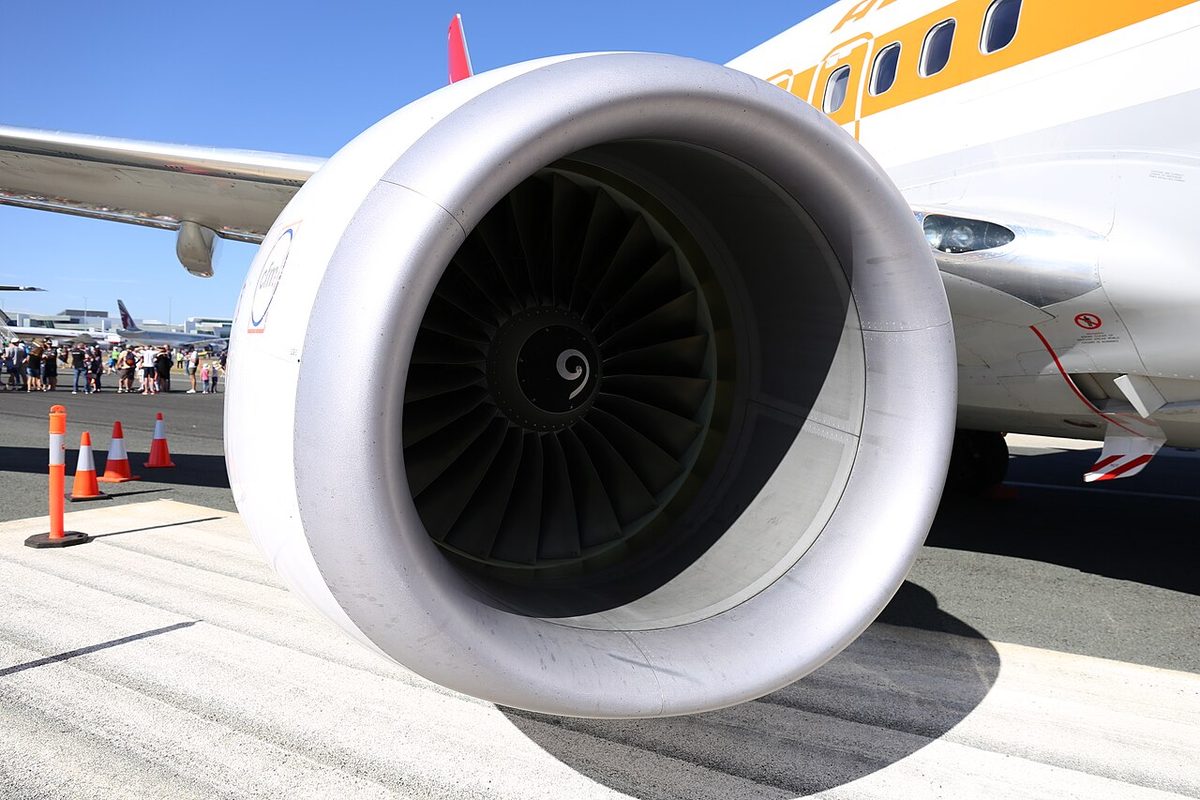
The engine anti-ice system keeps ice from forming on the engine cowl lip with the engine's own bleed air. It may be used on the ground and in flight. Each cowl anti-ice valve is electrically controlled and pressure actuated. Setting an ENGINE ANTI-ICE switch ON opens the valve, shows a green TAI indication on the engine display and sets the stall warning logic for icing conditions, which moves the stick shaker and the minimum manoeuvre speed bars on the airspeed indicator. The FMC's VREF is not adjusted automatically. At OFF, the stall warning logic returns to normal only if wing anti-ice has not been used in flight.
The panel has two lights per engine:
- The blue COWL VALVE OPEN light follows the transit convention: bright while the valve is in transit or disagrees with the switch, dim when the valve is open with the switch ON.
- The amber COWL ANTI-ICE light shows an overpressure in the duct downstream of the cowl anti-ice valve.
If a cowl valve fails to reach the commanded position, the COWL VALVE OPEN light stays bright blue and, after a short delay, the TAI indication turns amber. Engine anti-ice also has engine-side effects: approach idle is selected in flight whenever a cowl anti-ice switch is ON, and the limitations require engine ignition to be on during anti-ice operation.
Wing anti-ice
The wing anti-ice system heats only the three inboard leading edge slats of each wing; the leading edge flaps and the outboard slats are not protected. Bleed air flows through the slats and is exhausted overboard, and the system works with the slats in any position. The wing anti-ice control valves are AC motor operated, and their blue VALVE OPEN lights are bright in transit or disagreement and dim when open.
In flight, WING ANTI-ICE ON opens both valves and sets the stall warning logic for icing; once wing anti-ice has been used in flight, that logic stays set for the rest of the flight whatever the switch position. On the ground the system protects itself: with the switch ON, the valves open only while thrust on both engines is below the take-off warning setting and both distribution ducts are below their thermal switch temperature. If either condition is lost, the valves close but the switch stays ON, and they reopen automatically once thrust is reduced and the ducts have cooled. The switch trips OFF at lift-off, when the air/ground system goes to air mode.
These choices have operational consequences. VREF ICE, VREF 15 plus 10 kt, is used if engine anti-ice will be on for landing, if wing anti-ice has been used at any time in the flight, or if icing was encountered and the landing temperature is below 10 °C; the wind additive is then limited to 5 kt. Holding in icing conditions with any flap setting other than zero is prohibited. Window, probe and sensor heat are electrical and are described in probe heat, window heat and rain protection.
737 NG and 737 MAX
Among its differences from the 737-800 to the 737-8, the FAA Flight Standardization Board lists these. The BLEED TRIP OFF light becomes BLEED. The wing anti-ice valve alerts and the renamed cowl valve alert are amber instead of the NG's blue lights, and a new ENG ANTI-ICE alert is added. The LEAP-1B's engine control adds an icing idle speed. MAX crews therefore take the alert logic from their own FCOM rather than relying on the NG's bright blue cue; the figures and logic in this article are those of the NG FCOM.
Frequently asked questions
What does the DUAL BLEED light mean on the Boeing 737?
The amber DUAL BLEED light shows that the APU bleed air valve is open while an engine can also feed the duct: with the engine No. 1 BLEED switch ON, or with the engine No. 2 BLEED switch ON and the isolation valve open. APU and engine air then meet in the duct, and thrust must be limited to idle while the light is on. It is normal in the preflight configuration.
What causes a BLEED TRIP OFF light on the 737?
Excessive engine bleed air temperature or pressure. The related engine bleed air valve closes automatically and the amber BLEED TRIP OFF light comes on. The valve stays closed until the fault has cleared and the crew push the TRIP RESET switch, which also resets PACK and ZONE TEMP lights. On the 737 MAX the light is called BLEED.
When is the bleed isolation valve open on the Boeing 737?
With the ISOLATION VALVE switch in AUTO, the valve is closed when both engine BLEED switches are ON and both PACK switches are in AUTO or HIGH, keeping the left and right sides of the duct apart. It opens automatically if either engine BLEED switch or either PACK switch is set OFF. The APU BLEED switch has no effect on it. The switch is set to OPEN in the preflight and shutdown configurations.
What does the WING-BODY OVERHEAT light indicate on the 737?
A bleed air duct leak, sensed by overheat sensors. The left light covers the left engine strut, the left inboard wing leading edge, the left air conditioning bay, the keel beam and the APU bleed duct; the right light covers the right strut, right inboard leading edge and right air conditioning bay. The OVHT TEST switch checks the detector circuits.
Which parts of the Boeing 737 wing are anti-iced?
Only the three inboard leading edge slats on each wing. Bleed air flows through them and is exhausted overboard, and the system works with the slats in any position. The leading edge flaps and the outboard slats are not protected. On the ground the valves close if either engine's thrust exceeds the take-off warning setting or a duct overheats, and the switch trips OFF at lift-off.
Test yourself on B737 Bleed Air and Anti-Ice
The v1prep banks cover this topic in the B737 type-rating bank, with a worked explanation for every answer. EASA ATPL, PPL, IR and CPL, the FAA written tests and A320/B737 type ratings.
Start practising →Sources and further reading
- EASA Type Certificate Data Sheet IM.A.120, Boeing 737
- FAA Flight Standardization Board Report, Boeing 737
- EASA Easy Access Rules for Large Aeroplanes (CS-25), CS 25.1419 Ice protection and Appendix C
- 14 CFR 25.1438, Pressurization and pneumatic systems
- 14 CFR 25.1419, Ice protection
- FAA Aviation Maintenance Technician Handbook, Airframe (FAA-H-8083-31B), Chapter 15, Ice and Rain Protection
Library articles are written for study and exam preparation. They do not replace your aircraft's approved documentation, your operator's procedures or the regulations themselves.