Fire and Overheat Detection
A fire and overheat detection system senses abnormal temperatures in the designated fire zones of an aircraft, such as the engine nacelles and the APU compartment, and warns the crew on the flight deck, while testing itself and guarding against false warnings.
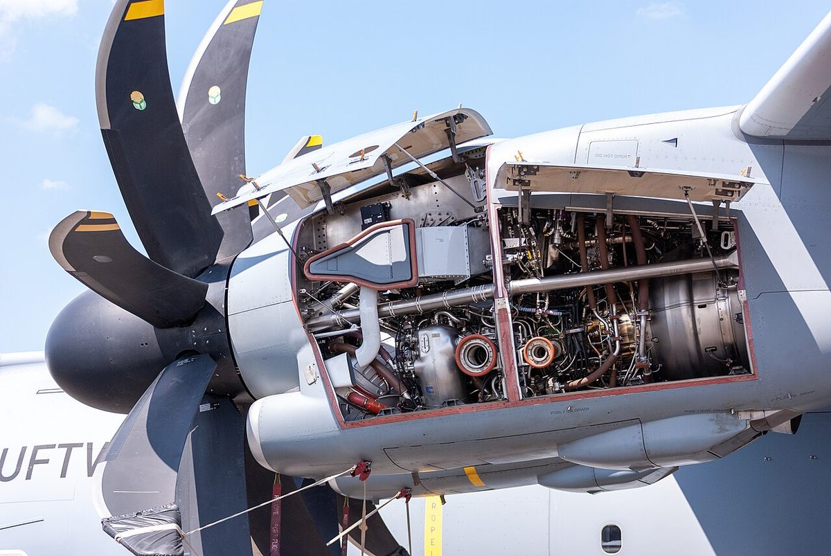
A fire and overheat detection system tells the crew about a fire or a dangerous rise in temperature in a part of the aircraft they cannot see: the engine nacelles, the APU compartment and, on some types, the main landing gear wheel wells. It has to meet two demands that pull against each other. It must detect a real fire quickly, anywhere in the zone, and it must almost never give a false warning, because the answer to an engine fire warning is to shut down a working engine.
Detection is the first half of fire protection. The second, fire extinguishing, is covered in engine fire protection; smoke detection in holds and lavatories, which works on different principles, in cargo and lavatory fire protection.
Fire detection requirements
Fire detection is required in the designated fire zones, the regions where a fire could start after a failure or leak of a component. CS 25.1181 and 14 CFR 25.1181 define them. They include the engine compartments, down to the compressor section of a turbine engine, and the APU compartment, and each must meet the fire protection requirements that run from CS 25.1185 to 25.1203. The last of these, CS 25.1203 and 14 CFR 25.1203, covers the detector systems.
ATPL texts summarise what a detection system must do:
- detect rapidly, wherever in the zone the fire starts;
- give an unmistakable warning on the flight deck, attention-getting rather than startling, that identifies the zone;
- be testable from the flight deck before flight, including its wiring and indications;
- not fire the extinguishers by itself, so that a false warning cannot waste the agent. The pilots discharge the engine bottles after confirming the warning; the APU on the ground, which may be unattended, is the usual exception.
The coverage differs between types:
| Zone | Airbus A320 | Boeing 737 NG | Embraer E190-E2 |
|---|---|---|---|
| Each engine | Two loops, A and B, with elements in the pylon nacelle, core and fan section | Two loops, each sensing both overheat and fire | Two loops, each with 2 × 4 pneumatic detectors in the core |
| APU | Two loops, one element each | One loop | Fire detection, with automatic shutdown on the ground |
| Main wheel well | None | One loop, no extinguisher | – |
On the A320neo with Pratt & Whitney PW1100G-JM engines, EASA accepted the fan compartment as a zone that is not a designated fire zone, so it has no detection or extinguishing; the LEAP-1A has two designated zones, the fan area and the core.
Continuous-loop fire wires
The classic engine detector is the continuous fire wire, a loop routed through the whole zone so that heat anywhere along it is sensed. ATPL texts call it the FFFD type, for "free from false detection". It is a fire sensing element made of a stainless steel tube with a central electrode, insulated from the tube by a temperature-sensitive material.
- In the resistance type, the insulation's resistance falls as it heats (a negative temperature coefficient), so more current leaks from electrode to tube until a set level triggers the warning.
- In the capacitance type, the capacitance between electrode and tube rises with temperature, and the control unit senses the extra charge. Its advantage is that a short circuit to earth, for example from a chafed element, does not produce a false fire warning, as it would in the resistance type.
Both reset themselves when the element cools. The loops are laid around each engine as a continuous double loop: normally both loops must sense fire before the warning is given, so a single faulty loop cannot cause a false alarm, and the system keeps working with a single loop failed, showing a loop fault instead.
Gas-filled pneumatic detectors
A gas-filled fire detector, or pneumatic detector, is a sealed stainless steel tube containing a core that absorbs gas. Gas is forced into the tube under pressure and partly absorbed before the tube is sealed. When the tube is heated, the core releases gas, the pressure rises quickly, and a pressure switch at the end of the tube signals the fire warning. The same detector also senses general overheat in the zone, for example a hot air leak from a bleed duct.
A useful property is its built-in fault detection. If the tube is broken, the gas escapes, and the same pressure switch senses the drop in pressure and signals a loop fault, which cannot be confused with a fire. Gas-filled detectors are also installed as double loops; the E190-E2 uses pneumatic detectors in its engine cores.
Differential expansion and melting link detectors
Older and more local detectors work at a single point rather than along a loop.
- A melting link fire detector holds a pair of contacts apart with a fusible plug. At a set temperature the plug melts and the contacts close the warning circuit. Its drawback is that it cannot reset: the warning stays on after the fire is out, so the crew cannot tell a burning engine from an extinguished one. It is found on older aircraft.
- A differential expansion fire detector has contacts on a spring bow inside an expansion tube. Heat makes the tube expand faster than the bow, pulling the contacts together; as it cools, they open again and the warning cancels. A short time delay stops vibration from triggering it.
Differential expansion detectors are often used to watch the engine's cooling air outlets and give an internal engine overheat (IEOH) warning. An IEOH warning points to a failure inside the engine, and it requires the engine to be shut down.
Flame detectors
A flame detector responds to light rather than heat. A photoelectric cell watches the protected area, and the visible or infrared radiation of an open flame changes the current through the cell and triggers the warning. Because it needs an open flame, which usually follows smoke, it is less common in aircraft than smoke detection.
Fire detection units and warnings
The loops of each zone are monitored by a fire detection unit (FDU) or equivalent control unit, which applies the warning logic. On the A320 the FDU gives a fire warning if:
- both loops detect a fire;
- one loop detects a fire and the other is failed;
- both loops break within 5 seconds of each other, the flame effect, since a fire can sever both loops almost at once;
- the crew press the FIRE TEST pushbutton.
A fire signal from one loop while the other is healthy gives no warning; a failed loop gives only a loop-fault caution. The 737 works in a similar way. With the OVHT DET switch in NORMAL, a single failed loop is deselected automatically, with no flight deck indication, and the other carries on alone; the amber FAULT light comes on only when both loops of an engine have failed. The switch can also select loop A or B to run the system as a single loop.

The warning itself is designed to be unmistakable:
- Aural: the fire bell on the 737; the continuous repetitive chime on the A320; a klaxon on some other types.
- Visual: master warning lights, such as the 737's two master FIRE WARN lights, the zone's fire handle or pushbutton lit red, and, on the A320 and most 737 variants, a fire light at the engine's fuel control, so that the crew identify the engine to shut down.
- Displays: the ECAM or EICAS fire warning, and on the E190-E2 a FIRE indication on the engine's ITT indicator.
The lit handle also unlocks the 737's engine fire switch, which is normally locked down to prevent an inadvertent shutdown. Pushing a master FIRE WARN light silences the bell and resets the system for further warnings, but the handle stays lit until the detector has cooled below its onset temperature. On the E190-E2, if the fire handle light goes out but the ENG FIRE message remains on EICAS, the fire is still present.
Engine overheat detection
An engine overheat is a temperature too high for normal operation but below that of a fire, for example from a hot gas or bleed air leak. On the 737 the same two loops provide both functions: as a detector warms to a first limit it signals an overheat, and at a higher temperature a fire. The overheat gives an amber ENG OVERHEAT light and master caution, with no bell. The recall items are to disengage the autothrottle and close the thrust lever; if the light stays on, the crew continue with the Engine Fire, Severe Damage or Separation checklist.
Separate overheat detection systems watch the hot air ducts. The A320 has leak detection loops along its bleed ducts, a single loop in the pylons and APU, a double loop in the wings; the 737's WING-BODY OVERHEAT lights cover the struts, wing leading edges, air conditioning bays, keel beam and APU duct. These give amber cautions and are answered by isolating the leaking duct rather than with a fire bottle (see bleed air and pneumatic systems).
Wheel well fire detection
Hot brakes after a rejected take-off or a heavy landing, hydraulic fluid and tyres make the main gear bay a fire risk. The 737 therefore has wheel well fire detection: a single loop in the main wheel well, which gives the fire bell, master FIRE WARN lights and a red WHEEL WELL light. There is no extinguisher and no detection in the nose wheel well; the procedure is to extend the landing gear so that the airflow cools the wheel well. The A320 has no wheel well fire detection. It monitors the temperature of each brake instead, with an ECAM caution when a brake exceeds 300°C, before an overheating brake can become a fire.
False fire warnings
A false fire warning is one with no fire behind it. Causes include a chafed or damaged loop shorting to the structure, failed components and, in smoke detectors, dust, condensation or gases given off by cargo. Dual-loop logic, capacitance-type elements, time delays and fault monitoring all reduce them.
In flight, though, the crew cannot prove a warning false. The design philosophy is that any fault which may give a false fire warning is treated as a real fire: the drill is flown, the bottles are fired as the procedure requires, and the aircraft lands. The investigation happens on the ground. Pre-flight tests support this trust. The 737's FAULT/INOP test checks the fault circuits, and the OVHT/FIRE test gives the full warning for every engine, the APU and the wheel well, while the A320's ENG FIRE TEST exercises detection and extinguishing indications for each engine. A zone whose test fails is not protected, and the minimum equipment list decides whether the aircraft may go.
Exam tip: four detector types appear in ATPL questions: melting link (cannot reset), differential expansion (resets, used for IEOH), continuous fire wire (FFFD, resistance or capacitance) and gas-filled (pressure rise means fire, pressure drop means loop fault). Detection never fires engine bottles automatically, and every fire warning is treated as real.
Frequently asked questions
How does an aircraft engine fire detection system work?
Sensing elements are routed through the engine's fire zones, usually as two independent loops. When a section of loop is heated beyond a set temperature, its electrical properties or internal gas pressure change, and a fire detection unit compares the two loops. If both report fire, or one reports fire while the other is known to be failed, the crew get a fire warning: an aural alarm, master warning lights and the lit fire handle or pushbutton.
Why do aircraft use two fire detection loops?
Two loops make the system both reliable and resistant to false alarms. Normally both loops must detect fire before the warning is given, so a single damaged or faulty loop cannot trigger it. If one loop fails, the logic switches to the remaining loop, so detection is kept. Only when both loops fail is the zone unprotected, which the system announces as a detection fault.
What is the difference between an engine fire warning and an engine overheat warning?
A fire warning is a red warning with a bell or chime and master warning lights, and it leads to the engine fire drill. An overheat, sensed on the Boeing 737 by the same loops at a lower temperature, is an amber caution. The 737 crew close the thrust lever, and only if the ENG OVERHEAT light stays on do they run the engine fire checklist.
Can an aircraft fire warning be false?
Yes. Damaged or chafed loops and faulty components can produce warnings without a fire, and smoke detectors can be fooled by dust or condensation. Designs reduce this with dual-loop logic and fault monitoring, but the crew cannot tell a false warning from a real one in flight. The rule is therefore to treat every fire warning as real and carry out the drill until the aircraft is on the ground and the cause has been investigated.
What is a continuous fire wire?
A continuous fire wire is a thin stainless steel tube with a central electrode, separated from the tube by a material whose resistance falls, or capacitance rises, as it heats. A fire anywhere along its length lets current or charge pass between electrode and tube, and the control unit gives a warning. It resets itself when it cools. ATPL texts call it FFFD, free from false detection.
Test yourself on Fire and Overheat Detection
The v1prep banks cover this topic in Aircraft General Knowledge (021), with a worked explanation for every answer. EASA ATPL, PPL, IR and CPL, the FAA written tests and A320/B737 type ratings.
Start practising →Sources and further reading
- 14 CFR 25.1203, Fire detector system
- 14 CFR 25.1181, Designated fire zones; regions included
- EASA Easy Access Rules for Large Aeroplanes (CS-25)
- EASA, Explanatory Note to ED Decision 2018/001/R, Part-FCL theoretical knowledge learning objectives (021 Airframe and Systems)
- FAA Aviation Maintenance Technician Handbook, Airframe (FAA-H-8083-31B), Fire Protection Systems
- FAA Aviation Maintenance Technician Handbook, Powerplant (FAA-H-8083-32B), Engine Fire Protection Systems
Library articles are written for study and exam preparation. They do not replace your aircraft's approved documentation, your operator's procedures or the regulations themselves.