A320 Bleed Air and Ice Protection
The A320 pneumatic system supplies high-pressure air, taken from the engine compressors, the APU or a ground cart, to the packs, the engine starters, the wing anti-ice and the water and hydraulic reservoirs; ice protection adds hot bleed air at the slats and engine intakes and electrical heat at the probes and windows.
The A320's pneumatic system delivers hot, high-pressure air wherever the aircraft needs it: to the air conditioning packs, the engine starters, the wing anti-ice, and the pressurisation of the water and hydraulic reservoirs. The same bleed air, together with electrical heating, protects the aircraft against ice. Both systems are largely automatic, but their logic, valves and thresholds are a favourite subject of type rating questions.
This article follows the air from the engine to its users, then describes the ice and rain protection. The general principles are covered in bleed air and pneumatic systems and thermal anti-icing; the packs in A320 air conditioning.
Pneumatic system overview
High-pressure air has three sources: the engine bleed systems, the APU load compressor and the HP ground connection. A crossbleed duct joins the engine 1 and engine 2 bleed systems and also receives air from the APU and the ground connection. Normally engine 1 supplies the left side and pack 1, engine 2 the right side and pack 2, and the crossbleed valve is closed, so a fault on one side affects only that side.
The crossbleed valve has two electric motors, one for automatic and one for manual operation. With the X BLEED selector at AUTO it opens when the APU bleed valve is open and closes when it closes, and it closes automatically on a leak signal except during engine start. OPEN and SHUT select it manually, for example OPEN for a crossbleed start, in which the running engine's bleed, with its thrust increased, turns the other engine's starter when no APU or ground air is available.
With the APU BLEED pushbutton ON, the APU bleed valve opens if there is no APU or left wing leak and the APU speed is at least 95 %. The crossbleed valve then opens (at AUTO) and the engine bleed valves close; with X BLEED SHUT, only the engine 1 bleed valve closes, since the APU air cannot reach the right side. A check valve stops air from other sources flowing back into the APU. APU bleed may not be used for wing anti-ice, nor at the same time as an HP air start unit. Its altitude limits are given in A320 APU.
Engine bleed and precooler
Bleed air is taken from the high-pressure compressor. It normally comes from the intermediate pressure (IP) port, which costs the least fuel; at low engine speed, when IP pressure is too low, the HP valve opens and air comes from the HP port, regulated to 36 ± 4 psi. The IP and HP ports are the 5th and 9th stages on the CFM56-5, and the 7th and 10th stages on the IAE V2500. An IP check valve stops HP air flowing back into the IP stage. The HP valve closes pneumatically on low or excessive upstream pressure, and electrically on upstream overpressure when the wing anti-ice is off, both packs are on and the aircraft is above 15,000 ft.
The bleed valve, also called the pressure regulating valve, follows. It is pneumatically operated and electrically controlled by its bleed monitoring computer, and it regulates the delivery pressure to 45 ± 5 psi at the precooler inlet. At high power up to FL100 the pressure may normally fluctuate between 38 and 56 psi. The valve closes pneumatically if the upstream pressure falls below 8 psi or the flow reverses, and electrically for overtemperature, overpressure, a leak, an open starter valve or APU bleed in use. It also closes when the crew select the ENG BLEED pushbutton OFF, which closes the HP valve as well and lights the white OFF light, or release the ENG FIRE pushbutton. If pressure regulation fails, an overpressure valve closes at 85 psi.
The precooler is an air-to-air heat exchanger cooled by fan air. A fan air valve, held closed by a spring without pressure, varies the cooling flow so that the bleed is delivered at about 200 °C.
Bleed monitoring computers
Two bleed monitoring computers (BMC 1 and BMC 2) control and monitor the system, each mainly for its own engine. Their main tasks are pressure and temperature monitoring and leak detection.
Leak detection uses sensing elements along the ducts: a single loop for each pylon and for the APU duct, and a double loop (A and B) in each wing. A wing leak is signalled when both loops detect it, or when one detects it and the other is inoperative. The thresholds are:
| Loop | Warning | Threshold |
|---|---|---|
| Wing | L(R) WING LEAK | 124 °C |
| APU | APU BLEED LEAK | 124 °C |
| Pylon | ENG 1(2) BLEED LEAK | 204 °C, engine running |
A leak closes every valve that could feed the area. A wing or pylon leak closes that side's bleed valve, lights its ENG BLEED FAULT light and closes the crossbleed valve (except during engine start); a left wing leak also closes the APU bleed valve. An APU leak closes the APU bleed and crossbleed valves (except during engine start) and lights the APU BLEED FAULT light, but does not shut the APU down. On the ground in hot weather, overheating detected around the wing bleed ducts can trigger a wing leak alert; during transits, keeping the slats at CONF 1 when the OAT is above 30 °C helps avoid it.
The ENG BLEED FAULT light comes on for overpressure downstream of the bleed valve, a bleed overheat, a leak on that side, or a bleed valve that has not closed during engine start or with APU bleed on. With the engine running, the caution triggers above 57 psi, or when the temperature exceeds 257 °C for 55 seconds, 270 °C for 15 seconds or 290 °C for 5 seconds.
If one BMC fails, the other takes over most monitoring, keeping the overpressure, overtemperature and wing leak warnings. The failed side loses its FAULT light, its automatic bleed valve closure and its engine bleed leak warning, and a BMC 1 failure also loses APU leak detection. If both fail, BLEED MONITORING FAULT is displayed.
ECAM BLEED page
The BLEED page shows the bleed system from the engines to the packs. Valves are drawn in line (open) or cross line (closed), green when their position agrees with the command and amber when it does not; the crossbleed valve in transit is shown in amber only. The engine number turns amber when N2 is below idle. The precooler inlet pressure turns amber below 4 psi or at the BMC overpressure threshold, and the precooler outlet temperature turns amber on the overheat thresholds above. The APU bleed valve is drawn cross line amber if it stays closed for more than 10 seconds with the APU running and APU BLEED ON. With wing anti-ice on, a bleed temperature below 150 °C gives the ENG BLEED LO TEMP caution. The pack indications on the same page are described in A320 air conditioning.

Wing anti-ice
Wing anti-ice heats the leading edges of the three outboard slats, slats 3, 4 and 5, on each wing; the inboard slats and the flaps are not protected, and neither is the horizontal stabiliser. Hot bleed air passes through one wing anti-ice shutoff valve (WAISOV) in each wing, both controlled by the single WING pushbutton, and is distributed along the slats by piccolo tubes, perforated pipes inside the leading edge.
The valves are pneumatically operated and electrically controlled and close if electrical power is lost. On the ground, selecting WING opens them for a 30-second test, after which they close; if they stay open more than 35 seconds, the WING A. ICE OPEN ON GND caution appears. A leak closes only the affected side's valve. A valve that fails to open gives the SYS FAULT caution and the amber FAULT light; one that fails to close after OFF gives L(R) VALVE OPEN; high pressure with the system on gives the HI PR advisory. With wing anti-ice selected, the FADEC raises the minimum idle and adjusts the thrust limits to provide enough bleed pressure.
The crew may switch the wing anti-ice on in icing conditions, defined as an OAT (on the ground and after take-off) or TAT (in flight) at or below +10 °C with visible moisture, such as cloud, fog with a visibility of 1,600 m (1 SM) or less, rain, snow, sleet or ice crystals, or an OAT at or below +10 °C on the ground when operating where surface snow, standing water or slush may be ingested by the engines or freeze on the engines, nacelles or probes. They must switch it on when there is evidence of ice accretion: ice on the visual ice indicator or on the wipers, or a SEVERE ICE DETECTED alert.
Engine nacelle anti-ice
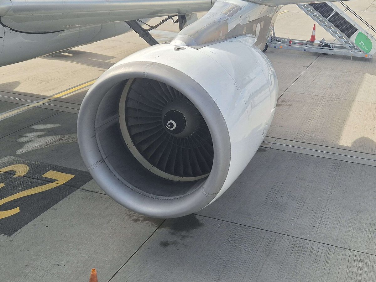
Each engine's air intake lip is heated by hot air bled from that engine's own HP compressor through a nacelle anti-ice valve. The supply is independent of the engine bleed valve, so it works with the ENG BLEED pushbutton OFF, but it can come from no other source: an engine that is not running has no nacelle anti-ice. The valve is spring-loaded open and opens if its electrical control is lost, so anti-icing continues as long as the engine supplies pressure. When it is open, the FADEC raises that engine's idle and adjusts its thrust limit.
Engine anti-ice must be on whenever icing conditions exist or are anticipated, except in climb and cruise with an SAT below −40 °C. On the ground in icing conditions, the engines should be run up to about 70 % N1 for 30 seconds at intervals of no more than 30 minutes, and again just before take-off, to shed ice.
An ice detection system with two probes on the lower forward fuselage gives advisory alerts only: ICE DETECTED (in flight at or above 1,500 ft, TAT below 10 °C, ice detected by at least one probe, with ENG anti-ice off) and SEVERE ICE DETECTED (heavy icing with WING anti-ice off). It never switches anti-ice on. An external visual ice indicator, lit at night, is mounted between the two windshields.
Probe and window heat
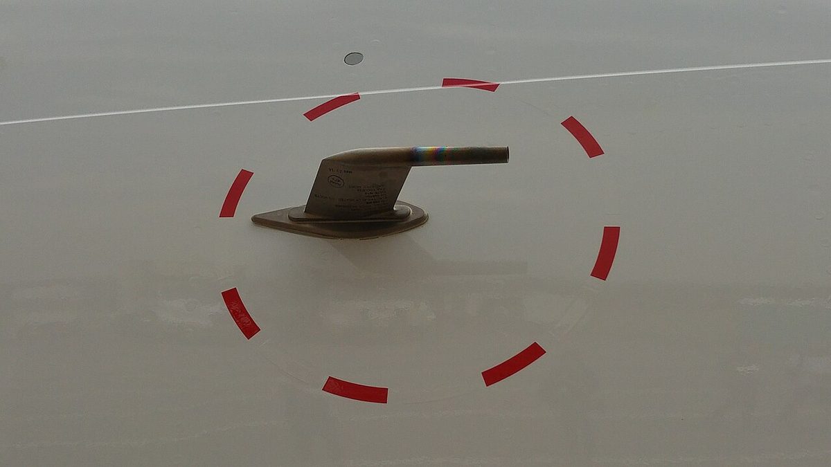
The air data probes are heated electrically: three pitot probes, six static probes, three angle-of-attack sensors and two TAT probes. Three independent probe heat computers (PHCs), captain, first officer and standby, control and monitor the heating. It comes on automatically when at least one engine is running or the aircraft is in flight; the PROBE/WINDOW HEAT pushbutton, normally at AUTO, can switch it on earlier. On the ground the pitots are heated at low power and the TAT probes are not heated, so that the temperature reading stays accurate. In the unreliable speed procedure, the first action of the affected ADR identification is PROBE/WINDOW HEAT ON.
The windshields and cockpit side windows are heated electrically under the control of window heat computers (WHCs), automatically with the same conditions as the probes. The windshields have a low power level on the ground and normal power in flight, for anti-icing and demisting; the side windows have a single level. A windshield heat failure gives a caution with single chime and MASTER CAUTION, a side window failure only an advisory. The drain masts are heated whenever electrical power is available, at a low level on the ground. The windshield wipers must not be operated above 230 kt.
Frequently asked questions
Where does A320 engine bleed air come from?
From the high-pressure compressor. Air is normally taken from an intermediate stage, the 5th on the CFM56-5 (the 7th on the IAE V2500), which costs less fuel. At low engine speed, when that pressure is too low, the HP valve opens and air comes from the 9th stage (10th on the V2500), regulated to 36 plus or minus 4 psi. The bleed valve then regulates the delivery to 45 plus or minus 5 psi and the precooler cools it.
What does the A320 BMC do?
The two bleed monitoring computers control and monitor the bleed system: the bleed valves, HP valves and crossbleed valve, overpressure and overheat, and leak detection by sensing loops along the ducts. A leak closes every valve that could feed it. If one BMC fails, the other takes over most monitoring, but the failed side loses its FAULT light, automatic bleed valve closure and engine bleed leak detection.
Which parts of the A320 wing are anti-iced?
Only the leading edges of the three outboard slats, slats 3, 4 and 5, on each wing. Hot bleed air is supplied through one wing anti-ice valve per wing and distributed by piccolo tubes. The inboard slats, the flaps and the tailplane have no anti-ice. On the ground, selecting the WING pushbutton opens the valves for a 30-second test only. APU bleed may not be used for wing anti-ice.
What happens to A320 engine anti-ice if electrical power is lost?
The nacelle anti-ice valve is spring-loaded open, so it opens and anti-icing continues as long as the engine is running and supplying bleed pressure. The wing anti-ice valves do the opposite: they need electrical power to stay open and close on its loss. Each engine's nacelle anti-ice uses only that engine's own bleed air, independent of its bleed valve, so it still works with the ENG BLEED pushbutton OFF.
When are the A320 probes heated?
Automatically when at least one engine is running or the aircraft is in flight; the PROBE/WINDOW HEAT pushbutton can switch the heating on earlier, for example before engine start in icing conditions. On the ground the pitots are heated at low power and the TAT probes not at all, so that the ground temperature reading stays accurate. Switching probe and window heat ON is also the first step in identifying the affected ADR in the unreliable speed procedure.
Test yourself on A320 Bleed Air and Ice Protection
The v1prep banks cover this topic in the A320 type-rating bank, with a worked explanation for every answer. EASA ATPL, PPL, IR and CPL, the FAA written tests and A320/B737 type ratings.
Start practising →Sources and further reading
- EASA, Explanatory Note to ED Decision 2018/001/R, Part-FCL theoretical knowledge learning objectives (021 Airframe and Systems)
- 14 CFR 25.1438, Pressurization and pneumatic systems
- EASA Easy Access Rules for Large Aeroplanes (CS-25), CS 25.1419 Ice protection and Appendix C
- 14 CFR 25.1419, Ice protection
- FAA Advisory Circular AC 91-74B, Pilot Guide - Flight in Icing Conditions
- FAA Aviation Maintenance Technician Handbook, Airframe (FAA-H-8083-31B), Chapter 15, Ice and Rain Protection, and Chapter 16, Cabin Environmental Control Systems
- EASA Type-Certificate Data Sheet EASA.A.064, Airbus A318/A319/A320/A321 (engines)
Library articles are written for study and exam preparation. They do not replace your aircraft's approved documentation, your operator's procedures or the regulations themselves.