Thermal Anti-Icing
Thermal anti-icing prevents ice by keeping a surface warm enough that ice cannot form or stay on it, using hot air bled from the engine compressors or electrical heating elements. On jet transports it protects the engine intake lips and part of the wing leading edge, and engine anti-ice is switched on before or on entering icing conditions.
Thermal anti-icing prevents ice with heat. A protected surface is kept warm enough that supercooled droplets striking it cannot freeze there, and the heat is applied continuously, which is what makes it anti-icing rather than de-icing. Jet transports rely on it almost entirely: hot air bled from the engine compressors heats the engine intake lips and part of the wing leading edge, and electrical elements heat the probes and windscreens. Boeing calls its bleed-air systems thermal anti-ice (TAI).
The method suits a jet because a jet has hot compressed air to spare, but that air is not free: air bled for anti-ice is air that no longer makes thrust. Knowing when each system must be on, what it protects and what it leaves bare is part of every jet pilot's cold-weather knowledge. The wider picture is in ice protection and ice detection; boots and fluid systems are covered in de-icing boots and fluid ice protection.
Principles of thermal anti-icing
ATPL texts list three ways of heating a surface: electrical resistance elements, hot oil (rarely) and hot air. The hot air usually comes from engine compressor bleed. Some turboprops instead heat outside air in a heat exchanger, where exhaust gas diverted around its tubes warms the air flowing through them, and smaller aircraft may use a combustion heater that burns fuel in a sealed chamber and warms ram air flowing around it (see cabin heaters and engine-driven blowers).
Anti-icing air comes from the same compressor tappings as the rest of the pneumatic system (see bleed air and pneumatic systems). Air from the higher stages is hotter, which is why the high-pressure bleed valve is scheduled to open when airframe anti-icing is selected: the protected surface needs heat to evaporate the water that strikes it. Temperature sensors in the leading-edge ducting are linked to valves in the supply ducts, which regulate the flow to hold the temperature within a set range.
Heating the leading edge does not make the water disappear. Droplets that strike a heated surface stay liquid and run back, and if they are not evaporated they can freeze again behind it, on skin that has no protection at all. This runback ice is a reminder that "anti-ice on" protects the intakes and part of the leading edge, not the whole aeroplane.

Bleed air wing anti-ice
In thermal wing anti-ice, hot bleed air is ducted into the wing leading edge. ATPL texts describe two arrangements. In one, the leading edge sections, including slats but not leading-edge flaps, have a second, inner skin a small distance behind the outer one, and the hot air flows through the gap, heating the outer skin from inside. In the other, the air is fed into a piccolo tube, a perforated pipe running along the span inside the leading edge, whose small holes direct jets of hot air onto the inner surface so that the heat is spread evenly. The spent air leaves through outlets in the skin or vents at the tip.
The wing anti-ice system of a jet transport protects only part of the span, and which part differs by type:
| Airbus A320 | Boeing 737 NG | Embraer E190-E2 | |
|---|---|---|---|
| Heated | Slats 3, 4 and 5, the three outboard slats on each wing | The three inboard slats on each wing; not the outboard slats or leading-edge flaps | The three outboard slats on each wing |
| Valves | One per wing, fail closed if electrical control power is lost | One AC motor-operated control valve per wing | Crossbleed valve opens automatically if a bleed source is lost |
| On the ground | Valves open for a 30-second self-test, then close | Valves open only while thrust is below the take-off warning setting and duct temperature is normal; the switch trips off at lift-off | With the selector at ON, wing anti-ice comes on only once airborne |
Neither the A320 nor the E190-E2 may use APU bleed air for wing anti-ice. On the A320 the wing system normally takes bleed from its own side's engine, through the crossbleed if that engine's bleed is off, and because wing anti-ice takes much more air than engine anti-ice, the FADEC raises the idle of both engines when it is selected, to keep enough bleed pressure. The 737's system is effective with the slats in any position.
Engine and nacelle anti-ice
Engine anti-ice, called nacelle anti-ice by Airbus and engine cowl anti-ice by Boeing, heats the intake lip of the nacelle with hot air from that engine's own compressor. Its purpose is to stop ice forming where it would disturb the airflow into the fan and, when it broke away, be swallowed by the engine. Ingested ice can bend or break compressor blades, cause a surge and, in the worst case, a flame-out (see gas turbine intakes and compressors). ATPL texts also list the inlet guide vanes and the nose cone or spinner among the areas that may need heating.
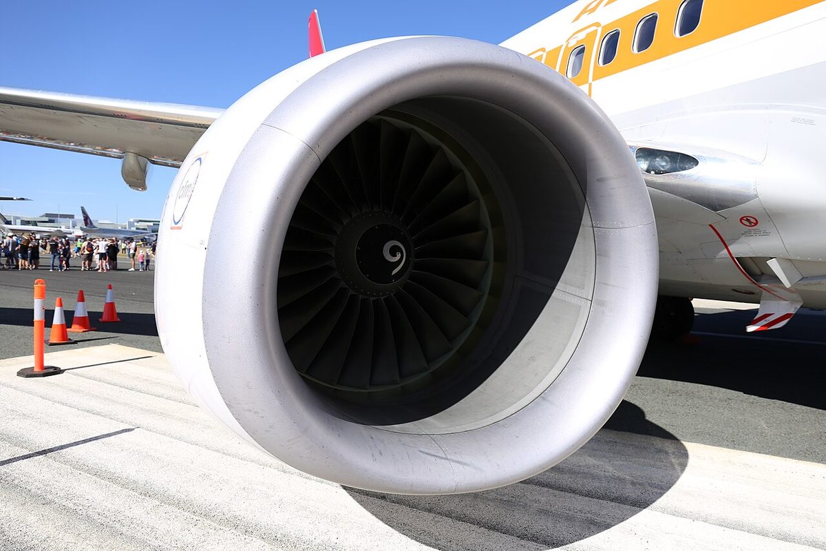
Each engine protects only itself. On the A320 the nacelle anti-ice air is tapped from the high-pressure compressor independently of the engine bleed valve, so it stays available with the ENG BLEED pushbutton off, but neither the other engine, the APU nor a ground cart can supply it. The nacelle anti-ice valve is spring-loaded open: if it loses electrical power, it opens, and the intake stays protected as long as the engine runs. Selecting engine anti-ice on the A320 also brings on continuous ignition automatically.
On the 737 NG each cowl anti-ice valve is electrically controlled and pressure actuated. A blue COWL VALVE OPEN light is dim when the valve is open as selected and bright while it is moving or disagrees with the switch; an amber COWL ANTI-ICE light warns of overpressure in the duct downstream of the valve; and a green TAI indication on the engine display confirms that the valve is open. With cowl anti-ice on, the engines go to approach idle in flight, and the limitations require engine ignition on during anti-ice operation. The E190-E2's cowl valve needs electrical power to stay closed, so it too fails open.
ATPL texts give the rule for using it: engine anti-ice is applied proactively, at an indicated outside air temperature of +10 °C or below with visible moisture, before any ice is seen. The margin above 0 °C is there because the air cools as it accelerates into the intake, so the lip can ice at positive outside temperatures.
Electrothermal ice protection
Electrothermal ice protection uses resistance elements, wire or sprayed metal, bonded to the surface or built into it, typically between layers of resin-impregnated glass cloth with an outer layer that resists rain erosion. ATPL texts give three-phase alternating current as the usual supply. A heater is a purely resistive load and does not care about frequency, so such loads can be fed from a frequency-wild alternator driven directly by the engine (see AC generators, CSD and IDG).
Electric heat is chosen where hot air cannot easily reach: probes, windscreens, drain masts, rotating propeller blades and the intakes of some turboprop engines. Run continuously, it anti-ices; switched on and off in timed cycles, it de-ices. One heater mat can do both, with continuously heated strips where ice must never form and cyclically heated areas between them, which saves power. ATPL texts give typical cycles for propeller and intake heaters: a fast cycle of 2 minutes at outside air temperatures between −6 °C and +10 °C, and a slow cycle of 6 minutes below −6 °C (see propeller ice protection). The probe and window heaters of jet transports are covered in probe heat, window heat and rain protection.
Operational use of anti-ice
The flight manual defines icing conditions and when each system is used. The A320's rules are typical. Icing conditions exist when the OAT on the ground and for take-off, or the TAT in flight, is at or below +10 °C with visible moisture: cloud, fog with visibility of 1,600 m (1 SM) or less, rain, snow, sleet or ice crystals. They also exist on the ground at +10 °C or below on ramps, taxiways and runways where surface snow, standing water or slush could be ingested by the engines or freeze on nacelles or probes.
- Engine anti-ice must be on whenever icing conditions exist or are anticipated, on the ground and in flight, except in the climb and cruise with the SAT below −40 °C.
- Wing anti-ice may be used in icing conditions to prevent accretion, and must be selected when there is evidence of ice: ice on the visual ice indicator or the wipers, or a SEVERE ICE DETECTED alert.
This matches the general ATPL rule: engines are protected proactively, the airframe at the onset of indicated icing. Other types differ in detail. On the E190-E2 the crew enters a take-off anti-ice setting on the MCDU, ENG between +5 °C and +10 °C with moisture and ALL below +5 °C, and in AUTO the systems come on when the ice detectors sense ice (see ice protection and ice detection). During long taxiing in icing conditions, periodic engine run-ups shed ice from the fan (see aircraft ground de-icing and anti-icing).
The cost is performance. Air bled for anti-icing reduces the mass flow through the core, so to hold the same thrust the fuel flow, the specific fuel consumption and the exhaust gas temperature all rise. Take-off performance is computed for the anti-ice configuration. Anti-ice also changes the aircraft's own margins. On the 737 NG, selecting engine or wing anti-ice sets the stall warning logic for icing conditions, moving the stick shaker and minimum manoeuvre speed bars; once wing anti-ice has been used in flight, that setting stays for the rest of the flight. VREF ICE, VREF 15 plus 10 kt, is then used for landing, as it is whenever engine anti-ice will be used during landing (see approach speeds and go-around climb requirements). The 737 limitations also prohibit holding in icing conditions with flaps extended.
Exam tip: engine anti-ice goes on at +10 °C or below with visible moisture, before ice forms; airframe protection at the onset of indicated icing. Selecting bleed air anti-ice raises SFC and EGT. Hot air protects intakes and leading edges; electric heat protects probes, windscreens and propellers.
Anti-ice failures and limitations
Thermal systems carry their own hazards. A heated leading edge with no cooling airflow can overheat, so the systems have temperature sensors, overheat warnings, automatic valve closure and ground inhibits; on some aircraft landing gear relays cut the valve supplies on the ground, leaving a TEST position for checks. The A320 limits wing anti-ice on the ground to its 30-second test and gives a WING A. ICE OPEN ON GND caution if the valves stay open more than 35 seconds. The 737 closes its wing valves on the ground if either engine's thrust exceeds the take-off warning setting or a duct thermal switch trips, and reopens them automatically when thrust is reduced and the ducts cool. A duct leak is a hazard too: on the A320 a detected wing leak closes only that side's valve.
Failures show as valve disagreements:
- A320: a wing anti-ice SYS FAULT, with an amber FAULT light, when a valve fails to open after selection; L (R) VALVE OPEN when one fails to close; and HI PR, an advisory without master caution, when high pressure is detected with wing anti-ice on.
- 737 NG: a bright blue VALVE OPEN light when a wing valve is in transit or disagrees with the switch, and an amber TAI indication when a cowl valve is not where commanded. The 737-8 shows its wing anti-ice valve alerts in amber.
- E190-E2: an A-I ENG 1 (2) FAIL caution when an engine anti-ice valve is closed although commanded open, or for a duct failure.
The fail-safe positions were chosen deliberately. On the A320 the nacelle valves fail open and the wing valves fail closed: an iced intake threatens the engine directly, and the crew get more warning of wing icing than of intake icing.
Finally, the systems are designed for the icing envelope in which the aircraft is certified, Appendix C of CS-25 and 14 CFR Part 25, under CS 25.1419. Supercooled large droplets strike behind the heated areas, and ice crystals at high altitude can affect engines and probes despite the heat, so both call for leaving or avoiding the conditions (see airframe icing). EU operating rules, CAT.OP.MPA.255, allow flight into expected or actual icing only in an aircraft certified and equipped for it.
Frequently asked questions
What is the difference between wing anti-ice and engine anti-ice?
Both usually use hot bleed air, but they protect different things and follow different rules. Engine anti-ice heats the intake lip of each engine with that engine's own bleed air, to stop ice forming where it would disturb the airflow or be swallowed by the engine; it goes on whenever icing conditions exist or are expected. Wing anti-ice heats part of the wing leading edge, usually some of the slats, and is used when ice accretion is likely or seen.
When must engine anti-ice be used?
On jet transports such as the A320, whenever icing conditions exist or are anticipated, on the ground and in flight: an OAT on the ground or TAT in flight of +10 °C or below with visible moisture, including fog with visibility of 1,600 m or less, or snow, slush or standing water on the ground. The A320 exempts the climb and cruise when the SAT is below −40 °C. It is selected before entering the moisture, not when ice appears.
Why is engine anti-ice needed at temperatures above freezing?
The air cools as it accelerates into the engine intake, so the intake lip and the parts behind it can be below 0 °C while the outside air is still a few degrees above. Ice can therefore form there at positive temperatures. ATPL texts and flight manuals use +10 °C with visible moisture as the threshold for that reason, and apply engine anti-ice before any ice is seen, because ice shed into the engine can damage the fan or compressor.
What is a piccolo tube in a wing anti-ice system?
It is a perforated pipe running along the span inside a heated leading edge or engine intake lip. Hot bleed air enters one end and escapes through many small holes along its length, so that jets of hot air strike the inside of the leading-edge skin evenly along the span instead of heating one spot. The spent air then leaves through outlets in the skin. The A320, for example, distributes its wing anti-ice air through piccolo tubes in slats 3, 4 and 5.
Does anti-ice reduce engine performance?
Yes. Air bled for anti-icing has been compressed by the engine but no longer passes through the combustion chamber and turbine, so to hold the same thrust the engine needs more fuel: specific fuel consumption and exhaust gas temperature both rise. Take-off performance is calculated for the anti-ice configuration. On the A320 the FADEC adjusts the idle and maximum thrust settings, and wing anti-ice, which takes the most air, has the largest effect.
Test yourself on Thermal Anti-Icing
The v1prep banks cover this topic in Aircraft General Knowledge (021), with a worked explanation for every answer. EASA ATPL, PPL, IR and CPL, the FAA written tests and A320/B737 type ratings.
Start practising →Sources and further reading
- FAA Advisory Circular AC 91-74B, Pilot Guide - Flight in Icing Conditions
- FAA Aviation Maintenance Technician Handbook, Airframe (FAA-H-8083-31B), Chapter 15, Ice and Rain Protection
- EASA Easy Access Rules for Large Aeroplanes (CS-25), CS 25.1419 Ice protection and Appendix C
- 14 CFR 25.1419, Ice protection
- EASA Easy Access Rules for Air Operations (CAT.OP.MPA.255, Ice and other contaminants, flight procedures)
Library articles are written for study and exam preparation. They do not replace your aircraft's approved documentation, your operator's procedures or the regulations themselves.