A320 Ventilation and Cargo Heating
A320 ventilation is the set of systems that cool the avionics equipment under the control of the avionics equipment ventilation controller (AEVC), extract air from the lavatories, galleys and batteries, and, where fitted, ventilate and heat the cargo compartments with cabin air and hot bleed air.
Besides the air conditioning that serves the cabin, the A320 has several smaller ventilation systems. The most important cools the avionics, whose computers dissipate a great deal of heat and depend on a forced flow of air. Others draw air out of the lavatories, galleys and battery area, and, on aircraft so equipped, ventilate and heat the cargo compartments.
These systems are almost entirely automatic, so type rating questions concentrate on their logic: which configuration the avionics ventilation adopts and why, what the BLOWER and EXTRACT pushbuttons do at OVRD, how avionics smoke is handled, and what closes the cargo isolation valves. The packs and the cabin temperature zones are described in A320 air conditioning, and the general principles of equipment cooling in cabin air distribution and equipment cooling.
Avionics ventilation overview
The ventilation system covers the avionics, the batteries, the lavatories and the galleys; cargo ventilation is a separate system. Avionics ventilation is managed by the avionics equipment ventilation controller (AEVC), which runs all the fans and valves of the system. It is fully automatic and uses two electric fans that run continuously whenever the aircraft is electrically supplied:
- the blower fan, which forces cooling air through the equipment;
- the extract fan, which draws the hot air out of it.
Whatever the configuration, part of the ventilation air is drawn from the cockpit through the various cockpit panels. A fan speed controller (FSC) sets the fan speed according to the ventilation air temperature: high speed above +40 °C, low speed below +35 °C.
The air is routed by a set of valves:
- the skin air inlet valve and the skin air outlet valve, which admit air from outside the aircraft and evacuate hot air from the avionics overboard;
- the skin exchange inlet and outlet bypass valves, which let air circulate between the avionics bay and the space under the cargo compartment floor, and the skin exchange isolation valve;
- the air conditioning inlet valve, which opens to let the air conditioning system supply fresh air to the avionics bay.
The space under the cargo floor acts as the skin heat exchanger: air circulated through it is cooled against the fuselage skin. The skin temperature sensor, whose measuring range is −50 °C to +80 °C, gives the AEVC the skin temperature on which its choice of configuration depends.
Note: "heat exchanger cooling mode" is a different thing. It is the degraded mode of an air conditioning pack whose air cycle machine has seized, in which the pack still cools the air through its heat exchangers at reduced flow. It has nothing to do with the avionics skin heat exchanger.
AEVC and ventilation configurations
The AEVC chooses one of three configurations according to the flight phase and the skin temperature, with the BLOWER and EXTRACT pushbuttons at AUTO.
| Configuration | When | Air path |
|---|---|---|
| Open circuit | On the ground, before take-off power, skin above +12 °C rising or +9 °C falling | Outside air in through the skin air inlet valve, out overboard through the skin air outlet valve |
| Closed circuit | On the ground after take-off power, and in flight with skin below +35 °C rising or +32 °C falling | Air recirculated and cooled through the skin heat exchanger |
| Intermediate | In flight with skin above +35 °C rising or +32 °C falling | Partly open circuit |
On the ground with the skin below the ground threshold, the closed configuration is used instead of the open one. If the skin temperature is outside the sensor's range, the AEVC selects the intermediate configuration until it returns within the range.
Exam tip: two pairs of thresholds are asked. On the ground the switch is at +12 °C rising and +9 °C falling; in flight at +35 °C rising and +32 °C falling. The gap between rising and falling values stops the valves from cycling.
Blower and extract fans
The VENTILATION panel has a BLOWER and an EXTRACT pushbutton, normally at AUTO, and each has an amber FAULT light:
- BLOWER FAULT comes on for low blowing pressure, a duct overheat, a failure of the computer's power supply or a smoke warning.
- EXTRACT FAULT comes on for low extract pressure, a computer power supply failure or a smoke warning.
Only the BLOWER light covers a duct overheat. If either warning occurs on the ground with the engines stopped, the external horn sounds to alert the ground crew.
Selecting BLOWER to OVRD stops the blower fan while the extract fan keeps running; the system goes to the closed-circuit configuration and adds air from the air conditioning system. Selecting EXTRACT to OVRD puts the extract fan under the direct control of its pushbutton, and both fans keep running.
If the AEVC itself fails, both FAULT lights come on and both pushbuttons are set to OVRD. The blower fan, the skin exchange inlet bypass valve and the skin air outlet valve then take their smoke configuration positions, the skin air inlet, skin exchange isolation and outlet bypass valves stay where they were, and the extract fan keeps running.
On the ECAM CAB PRESS page the VENT title is normally white and turns amber with a BLOWER FAULT, an EXTRACT FAULT or an AVNCS SYS FAULT; the BLOWER and EXTRACT legends turn amber with their own faults, and the INLET and OUTLET legends turn amber when the corresponding valve has failed.
The avionics cooling depends on the ambient temperature as well. On the ground, with normal avionics ventilation, the aircraft's own electrical power may be used without time limit when the OAT is 49 °C or below, but for at most 2 h between 49 and 55 °C, 1 h between 55 and 60 °C and 0.5 h between 60 and 64 °C.
Avionics smoke configuration
A single smoke detector sits in the air extraction duct of the avionics ventilation. When it detects smoke for more than 5 seconds, the crew get a single chime, the MASTER CAUTION light and the ECAM AVIONICS SMOKE caution, the SMOKE light in the GEN 1 LINE pushbutton on the EMER ELEC PWR panel, and the FAULT lights of both the BLOWER and the EXTRACT pushbuttons. Avionics smoke is a caution, not a warning: the continuous repetitive chime is kept for fires.
With both pushbuttons at OVRD, the avionics smoke configuration, the blower fan stops and the extract fan keeps running; cooling air comes from the air conditioning system and is then exhausted overboard. The equipment is still cooled, and the air, with any smoke it carries, leaves the aircraft rather than being recirculated. The detection and the related procedures are covered in A320 fire and smoke protection, and the electrical smoke configuration in A320 electrical system.
Selecting the DITCHING pushbutton closes, among other openings, the avionics ventilation inlet and extract valves, which lie below the flotation line (see A320 pressurisation).
Battery, lavatory and galley extraction
The batteries are ventilated without a fan: a venturi in the aircraft skin draws air from the space around them and vents it overboard.
A lavatory and galley extraction fan draws ambient cabin air through the lavatories and galleys and exhausts it near the outflow valve. It runs continually whenever electrical power is available. The flow has two other uses: the cabin zone temperature sensors of the air conditioning sit in the lavatory extraction circuit and the galley ventilation system, and each lavatory's smoke detector sits in its air extraction duct.
Cargo ventilation
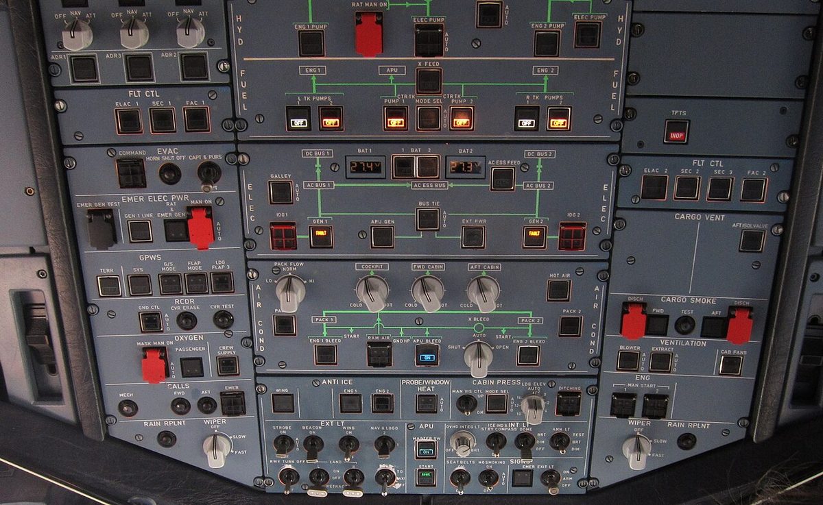
Cargo ventilation and heating are not fitted alike on every A320. The aircraft in the photograph above, for example, has a CARGO VENT panel with a single AFT ISOL VALVE pushbutton, and no forward isolation valve pushbutton or cargo temperature selector. The sections below describe forward and aft ventilation and heating; which of them a given aircraft has depends on its fit.
Cargo ventilation uses cabin air. An extraction fan draws air from the forward or aft cargo compartment and exhausts it overboard, and air from the cabin flows in to replace it. Each compartment has an inlet isolation valve and an outlet isolation valve, the cargo isolation valves.
Forward compartment. Cabin air enters through the inlet isolation valve, driven either by the extraction fan or, in flight, by the differential pressure. A venturi in the skin discharges it overboard through the outlet isolation valve. On the ground, or in flight with a differential pressure of 1 psi or less, the controller opens the isolation valves and then starts the fan. In flight above 1 psi it stops the fan, and the differential pressure alone keeps the air moving.
Aft compartment. Cabin air enters through the inlet isolation valve, driven by an extraction fan, and leaves through the outlet isolation valve and then overboard through the outflow valve. With the isolation valves fully open, the fan runs continuously on the ground and in flight.
The controls are the FWD and AFT ISOL VALVE pushbuttons. At AUTO the isolation valves open and the extraction fan runs, provided no smoke is detected. At OFF the isolation valves and the trim air valve close and the fan stops. The amber FAULT light, with its ECAM caution, comes on when the inlet or the outlet valve is not in the selected position.
The controller also closes the isolation valves and stops the fan by itself when the cargo smoke detection unit detects smoke in that compartment, which stops smoke spreading through the ventilation system; the cargo smoke test closes them too. DITCHING closes the forward cargo outlet isolation valve and stops the extraction fan.
Cargo heating
Where cargo heating is fitted, the temperature is regulated by mixing hot bleed air with the cabin air that flows through the compartment.
- The aft cargo heating uses hot engine bleed air taken upstream of the packs, through its own cargo pressure regulating valve, pneumatically operated and electrically controlled from the HOT AIR pushbutton on the CARGO HEAT panel.
- The forward cargo heating uses the same hot bleed air as the cockpit and cabin temperature control, its pressure regulated by the cockpit and cabin hot air pressure regulating valve.
In each case a cargo trim air valve, modulated electrically by the controller, adds the amount of hot air the temperature selector demands, upstream of the cargo inlet. The selectors run from about 5 °C at COLD through about 15 °C at the middle position to about 26 °C at HOT. The actual temperature in the bulk compartment may be up to 10 °C lower than selected, depending on the flight duration and the outside temperature.
The protection works in two steps on the inlet temperature:
| Inlet temperature | Action |
|---|---|
| Above 70 °C | The trim air valve closes |
| 88 °C | Duct overheat: the pressure regulating valve closes, HOT AIR FAULT light and ECAM caution |
After an overheat the valve stays closed until the crew reset the system. The FAULT light goes out once the temperature is below 70 °C and OFF is selected; selecting the pushbutton back to ON then resets the system. HOT AIR at OFF closes the pressure regulating and trim air valves and resets the fault circuit.
The cargo section of the ECAM COND page shows the duct inlet temperature, green and amber at 80 °C or more; the inlet and outlet isolation valves, in line green when open and cross line amber when closed; the trim air valve as H (hot, open) or C (cold, closed); and the hot air pressure regulating valve, in line amber if it has failed open.
Exam tip: cargo heating mirrors the cabin trim air. Hot air is only ever added, the trim air valve shuts at 70 °C, the pressure regulating valve at 88 °C, and the reset needs the temperature back below 70 °C.
Frequently asked questions
What are the avionics ventilation configurations on the A320?
There are three. Open circuit is used on the ground when the skin is warm (above +12 degrees C rising or +9 degrees C falling): outside air is blown through the equipment and dumped overboard. Closed circuit is used in flight and on the ground after take-off power: the air is recirculated and cooled through the skin heat exchanger. Intermediate, a partly open circuit, is used in flight when the skin is above +35 degrees C rising or +32 degrees C falling.
What happens when the A320 BLOWER and EXTRACT pushbuttons are set to OVRD?
With the BLOWER at OVRD the blower fan stops, the extract fan keeps running, and the circuit closes with air conditioning air added. With both pushbuttons at OVRD, which is the avionics smoke configuration, cooling air comes from the air conditioning system and is then exhausted overboard, again with the blower fan stopped and the extract fan running. The equipment is thus still cooled while the air is dumped overboard.
Why does the external horn sound for an A320 ventilation fault?
If a BLOWER or EXTRACT warning occurs on the ground while the engines are stopped, the external horn sounds so that people outside the aircraft are alerted. Avionics cooling matters on the ground: in normal ventilation, the aircraft's own electrical power may be used for at most 2 h when the OAT is between 49 and 55 degrees C, and for less above that.
How is the A320 cargo compartment heated?
Where cargo heating is fitted, hot bleed air is mixed into the cabin air that flows through the compartment. A cargo trim air valve, modulated by the controller to meet the temperature selected on the CARGO HEAT panel (about 5 degrees C at COLD to about 26 degrees C at HOT), adds hot air upstream of the cargo inlet. The trim air valve closes if the inlet temperature passes 70 degrees C, and the hot air pressure regulating valve closes at 88 degrees C.
What happens to A320 cargo ventilation when smoke is detected in the hold?
The controller closes that compartment's inlet and outlet isolation valves and stops its extraction fan, which stops smoke spreading through the ventilation system. The same happens when the crew select the ISOL VALVE pushbutton OFF, which also closes the cargo trim air valve.
Test yourself on A320 Ventilation and Cargo Heating
The v1prep banks cover this topic in the A320 type-rating bank, with a worked explanation for every answer. EASA ATPL, PPL, IR and CPL, the FAA written tests and A320/B737 type ratings.
Start practising →Sources and further reading
- EASA, Explanatory Note to ED Decision 2018/001/R, Part-FCL theoretical knowledge learning objectives (021 Airframe and Systems)
- EASA Easy Access Rules for Large Aeroplanes (CS-25), CS 25.831 Ventilation and CS 25.857 Cargo compartment classification
- 14 CFR 25.831, Ventilation
- 14 CFR 25.857, Cargo compartment classification
- FAA Aviation Maintenance Technician Handbook, Airframe (FAA-H-8083-31B), Chapter 16, Cabin Environmental Control Systems
- EASA Type Certificate Data Sheet EASA.A.064, Airbus A318, A319, A320, A321
Library articles are written for study and exam preparation. They do not replace your aircraft's approved documentation, your operator's procedures or the regulations themselves.