Trim Systems
A trim system removes the steady force a pilot would otherwise hold on the controls. Jet transports trim in pitch by moving the whole horizontal stabiliser with a screwjack, and in yaw by moving the rudder's neutral position, so that the aeroplane holds its flight path hands-off.
An aeroplane is in trim when it holds its attitude and flight path with no force on the controls. Trim systems keep it there as conditions change. A light aeroplane does it with a tab on the elevator; a jet transport moves its whole horizontal stabiliser through a screwjack, and trims in yaw by moving the rudder's neutral position. How tabs, spring bias and hinge moments work is covered in control balance, tabs and trim; this article is about the jet systems and the way crews use them.
Pitch trim on a transport is powerful. The stabiliser is a large surface with great authority over pitch, and it is set before every take-off from the load sheet. That power is why a mis-set take-off trim, a worn stabiliser drive or a runaway trim motor can each become an emergency.
Purpose of trim
The force a pilot must hold changes whenever the balance of pitching moments changes, so pitch trim is needed after changes of:
- Speed, because the elevator deflection needed for balance changes with it;
- Power or thrust, whose line of action and slipstream change the pitching moment;
- Centre of gravity, as fuel burns and as passengers or cargo move;
- Configuration, as flaps, slats and landing gear move.
Yaw trim is needed mainly for asymmetric thrust after an engine failure, and roll trim least of all. The pilot sets the attitude with the controls first and then trims the remaining force away.
| Method | How it trims | Typical use |
|---|---|---|
| Trim tab | An air load on the tab holds the surface | Light and older aeroplanes |
| Spring bias | An adjustable spring cancels the held force | Small aeroplanes, often for rudder trim |
| Feel datum | Moves the neutral point of an artificial feel unit | Powered controls, rudder and aileron trim |
| Trimmable stabiliser | Changes the incidence of the whole tailplane | Pitch trim on jet transports |
Whatever the method, a trim mechanism must not be back-driven by the air load, or the trim setting would drift with every change of speed. A manually operated trim tab is therefore irreversible: the screw or worm drive between trim wheel and tab holds it wherever it is set, even though the control it sits on is reversible.
Trimmable horizontal stabiliser
A trimmable horizontal stabiliser (THS) trims by changing the incidence of the whole tailplane. The elevators hinged behind it stay close to neutral, keeping their full travel for manoeuvring, and a stabiliser set at the right incidence makes less drag than an elevator held deflected. Its large authority copes with the CG changes of a long flight and with the pitch changes of flaps. On the A320 the THS moves from 13.5° nose-up to 4° nose-down, and the elevators move 30° up and 17° down.
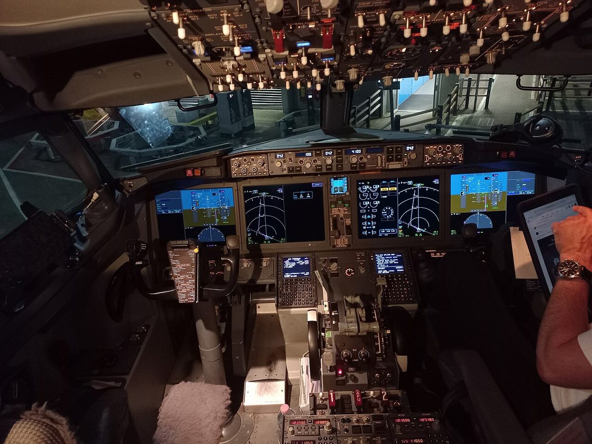
The Boeing 737 trims its stabiliser in several ways:
- Main electric trim from switches on each control wheel; both switches must be pushed together, and doing so disengages the autopilot. Main electric and autopilot trim run at a higher speed with the flaps extended and a lower one with them up.
- Autopilot trim from the flight control computers, which also provide speed trim, a speed stability augmentation for low weight, aft CG and high thrust with the autopilot off.
- Manual trim with the stabiliser trim wheels on the control stand, which drive the stabiliser through cables and override every other input. The wheels rotate whenever the stabiliser moves, and grasping a wheel stops it.
The authority differs by input. Main electric trim covers 0.05 to 14.5 units with the flaps extended and 3.95 to 14.5 units with them retracted, autopilot trim 0.05 to 14.5 units, and manual trim −0.2 to 16.9 units, so the wheels can reach settings that the motors cannot. Column-actuated cutout switches stop main electric and autopilot trim when the column is moved against the trim direction, and an override switch bypasses them. On the NG the two STAB TRIM cutout switches isolate main electric trim and autopilot trim, and an amber STAB OUT OF TRIM light shows, with the autopilot engaged, that it is not trimming properly. Mach trim works differently: above M 0.615 it moves the elevators relative to the stabiliser by repositioning the elevator feel and centring unit.
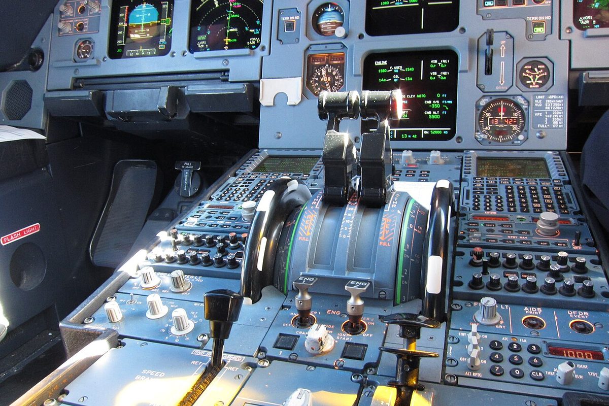
On the Airbus A320 the computers trim automatically in normal and alternate law, so in flight the pilot does not trim in pitch. ELAC 2 normally drives the THS through the first of three electric motors, with ELAC 1 or the SECs and the other motors as backups. The mechanically interconnected pitch trim wheels on the pedestal drive the THS whenever the green or yellow hydraulic system is working, and they have priority over electrical control; turning them disconnects the autopilot. In direct law auto-trim is lost and USE MAN PITCH TRIM appears in amber on the PFD, and in mechanical backup the pilot controls pitch with the trim wheel alone. After nosewheel touchdown, once the pitch attitude has been below 2.5° for more than 5 seconds, the THS resets to zero automatically.
Screwjack stabiliser drive
The stabiliser is hinged to the fuselage and its incidence is changed by a screwjack, also written screw jack or called a jackscrew: a threaded shaft turning in a nut attached to the stabiliser. Turning the shaft drives the nut along it and tilts the stabiliser. The drive must not let the air load turn the screw backwards, or the stabiliser would creep away from its setting; some screw drives can be back-driven by air loads once their power is removed, so designs hold the surface positively, often with brakes. On the 737 the stabiliser is held in position by two independent brake systems, and the trim wheels drive it through cables. On the A320 the screwjack is turned by two hydraulic motors, which are controlled by one of the three electric motors or by the mechanical trim wheel.
Because the trim wheels move the stabiliser against its air load, manual trimming gets harder as airspeed rises. After the 737 MAX accidents, regulators required an analysis and test of the trim wheel forces, and the revised runaway stabiliser and stabiliser trim inoperative checklists now note that reducing airspeed eases manual trimming. Boeing also defines manual trim techniques, including two pilots working together, and the FAA's 737 training standard requires electric and manual stabiliser trim and runaway stabiliser training at least once every 36 months in recurrent training.
Wear and lubrication of the screwjack are therefore critical. On 31 January 2000 Alaska Airlines Flight 261, a McDonnell Douglas MD-83, dived into the Pacific Ocean off California, killing all 88 people on board, after the threads of the nut in its stabiliser trim jackscrew assembly failed and the stabiliser was no longer held. The NTSB found that the threads had worn away through insufficient lubrication, and that lengthened intervals between lubrications and between wear checks had let the wear progress undetected.
Warning: a trim system that will not move, or moves without being commanded, is handled by the checklist. Never try to overpower a runaway with the elevator alone and leave the trim running: on the 737, stopping it with the cutout switches or the trim wheel is part of the recall items.
Stabiliser trim green band
Before take-off the stabiliser is set to a value computed for the take-off CG, from the load sheet or the performance data. The stabiliser trim green band is the range of settings allowed for take-off, marked on the trim indicator. A setting too far nose-down makes rotation heavy and slow; too far nose-up makes it light and quick, with a risk of a tail strike. Trim mis-set from an incorrect CG has caused tail strikes and rotation problems.
The crew set and cross-check the value. On the 737 the before-start procedure sets the stabiliser trim for take-off and verifies it is in the green band, with aileron and rudder trim at zero. On the A320 the pitch trim wheels are set after engine start to the THS value for the take-off CG, and the THS is among the take-off data the crew cross-check. On the ground the A320's computers would place the THS at 0°, inside the green band, but a setting entered manually by the crew takes priority for the take-off.
The take-off configuration warning is the backstop. On the 737 an intermittent horn sounds if take-off is attempted with the stabiliser trim outside the take-off range. On the A320 CONFIG PITCH TRIM and a PITCH TRIM/MCDU/CG DISAGREE warning, which compares the trim with the CG entered in the MCDU, respond both to the T.O CONFIG test and to take-off power. On the E190-E2 a pitch trim outside the green range triggers the take-off configuration warning.
Exam tip: the green band is a range for take-off, not a target. The setting comes from the CG; the band only shows that it is a sensible take-off value.
Rudder trim
Rudder trim removes a steady pedal force, chiefly the large one needed for asymmetric thrust after an engine failure, which it relieves once the aeroplane is stable, and small out-of-trim forces in the cruise. On a small aeroplane it may be a tab or a spring bias. On powered controls it moves the neutral point of the rudder's artificial feel, so the rudder holds the trimmed deflection with the pedals free.
On the A320 a rotary RUD TRIM selector on the pedestal drives the rudder trim actuator, which moves the neutral point of the artificial feel by the equivalent of one degree of rudder travel per second; the RESET pushbutton orders zero trim at 1.5° per second. Motor 1, controlled by FAC 1, normally powers it, with FAC 2 and motor 2 synchronised as backup. With the autopilot engaged the selector and reset are inactive and the flight management and guidance computer (FMGC) computes the rudder trim orders. In a normal cruise at about M 0.77, flying straight with the autopilot engaged and symmetrical thrust and fuel, the rudder trim should stay between 1° right and 2.3° left. The A320 has no aileron trim control; its control laws handle lateral trim.
On the Boeing 737 the rudder trim control is spring-loaded to neutral and trims the rudder electrically when rotated, and an OFF flag shows that the trim indicator has failed. The 737's aileron trim switches reposition the aileron neutral control position, but aileron trim with the autopilot engaged is prohibited, because the autopilot hides the out-of-trim condition, which then appears as an abrupt roll when it is disengaged. On the E190 E1 the recall action for a roll or yaw trim runaway is to press and hold the autopilot disconnect button, which also interrupts trim.
Pitch trim runaways, including the 737 runaway stabiliser procedure, are described in landing gear, flap and trim malfunctions.
Frequently asked questions
What is the stabiliser trim green band?
The green band is the range of stabiliser trim settings allowed for take-off, marked beside the trim indicator. The crew set the take-off trim worked out for the aeroplane's centre of gravity and check that it lies within the band. A setting outside it triggers the take-off configuration warning when take-off thrust is set, because a badly mis-set stabiliser can make rotation too heavy or too light and has caused tail strikes and rotation problems.
Why do jet airliners trim with a movable stabiliser?
A trimmable horizontal stabiliser changes the incidence of the whole tailplane, so it can produce the large tail loads needed as fuel burn moves the centre of gravity and as flaps and speed change. The elevators stay close to neutral with their full travel available for manoeuvring, and the drag is lower than with an elevator held deflected by a tab.
What is a screwjack in a stabiliser trim system?
A screwjack, or jackscrew, is a threaded shaft turning in a nut attached to the horizontal stabiliser. Trim motors or the manual trim wheel turn the shaft, the nut travels along it and the stabiliser's incidence changes. Brakes or the design of the drive stop the air load from driving it backwards, so the stabiliser stays where it is set. Its wear and lubrication are critical: worn nut threads caused the loss of Alaska Airlines Flight 261 in 2000.
How does rudder trim work on a jet?
On powered controls rudder trim moves the neutral point of the rudder's artificial feel, so the rudder holds the trimmed deflection with no pedal force. On the A320 a rotary RUD TRIM selector moves the neutral point at one degree of rudder per second, and a RESET pushbutton returns it to zero. On the Boeing 737 a spring-loaded rudder trim control trims electrically. Rudder trim relieves the pedal force after an engine failure once the aeroplane is stable.
What are the first actions for a runaway stabiliser on the Boeing 737?
Hold the control column firmly, disengage the autopilot and autothrottle, control pitch attitude with the column and airspeed with the thrust levers, and use main electric trim to reduce the column force. If the runaway continues, both STAB TRIM cutout switches go to CUTOUT, and if it still continues the pilot grasps and holds the stabiliser trim wheel. Manual trimming is then easier at lower airspeed.
Test yourself on Trim Systems
The v1prep banks cover this topic in Aircraft General Knowledge (021), with a worked explanation for every answer. EASA ATPL, PPL, IR and CPL, the FAA written tests and A320/B737 type ratings.
Start practising →Sources and further reading
- EASA Easy Access Rules for Large Aeroplanes (CS-25), CS 25.677 Trim systems
- 14 CFR 25.677, Trim systems
- NTSB AAR-02/01, Loss of Control and Impact with Pacific Ocean, Alaska Airlines Flight 261, McDonnell Douglas MD-83, 31 January 2000
- FAA, Summary of the FAA's Review of the Boeing 737 MAX (November 2020)
- EASA, Boeing 737 MAX Return to Service Report (January 2021)
- FAA Flight Standardization Board Report, Boeing 737
- FAA Pilot's Handbook of Aeronautical Knowledge (FAA-H-8083-25), Chapter 6, Flight Controls
Library articles are written for study and exam preparation. They do not replace your aircraft's approved documentation, your operator's procedures or the regulations themselves.