Semiconductors and Logic Gates
A semiconductor is a material, such as silicon, whose conductivity lies between that of a conductor and an insulator and can be controlled by doping. Joined into diodes and transistors, and combined into logic gates on integrated circuits, semiconductors perform the rectifying, switching and computing tasks of modern aircraft systems.
A modern airliner carries thousands of semiconductor devices. Diodes turn the generators' AC into DC and stop current flowing the wrong way; transistors switch power without moving contacts and turn the battery's DC into emergency AC; and integrated circuits holding millions of transistors, arranged as logic gates, run the flight management, flight control, engine control and display computers.
A pilot does not repair any of this, but examination syllabuses expect an understanding of how a diode blocks current, what a transistor does and how a logic gate combines conditions. The same logic appears, in plain words, in every system description that says a contactor closes "if" one condition "and" another are met. This article covers the devices; the computers built from them are described in avionics computers and data buses.
Semiconductors and doping
Materials are classed by how readily they conduct. Conductors such as silver, copper and gold have many free electrons; insulators such as glass and mica have very few. A semiconductor lies in between. The two classic semiconductors are silicon (Si) and germanium (Ge). In their pure state at room temperature they have few free electrons and behave more like insulators than conductors.
Their conductivity is greatly increased, and made controllable, by doping: adding a small, precisely measured quantity of an impurity to the pure crystal.
- N-type material is doped with atoms that have one more outer electron than the semiconductor needs to bond, such as phosphorus or arsenic. The spare electrons are free to move, so the majority charge carriers are negative electrons.
- P-type material is doped with atoms that have one electron too few, such as boron. Each missing electron leaves a hole, a vacancy that behaves like a positive charge as neighbouring electrons move into it. The majority carriers are holes.
Either type is electrically neutral as a whole; doping only supplies mobile carriers. The useful properties appear where P-type and N-type material meet.
The PN junction and depletion region
A PN junction is the boundary between P-type and N-type regions formed in a single crystal. At the moment they meet, free electrons from the N side diffuse across into the P side and fill holes there, while holes diffuse the other way. Near the boundary the mobile carriers cancel out, leaving a thin layer that contains only the fixed, charged impurity atoms and no free carriers: the depletion region.
The fixed charges on either side of the depletion region set up a built-in barrier potential that stops further diffusion. Current can cross the junction only if an external voltage overcomes that barrier, and it can do so in one direction only. That one-way property is the basis of the diode.
Diodes and forward and reverse bias
A junction diode is a single PN junction with a lead from each side, the anode on the P side and the cathode on the N side.
- In forward bias, the P side is connected to the positive of the supply and the N side to the negative. The applied voltage pushes carriers towards the junction, narrows the depletion region and overcomes the barrier, and current flows freely once the small forward voltage of the junction is exceeded.
- In reverse bias, the connections are the other way round. Carriers are drawn away from the junction, the depletion region widens, and only a tiny leakage current flows. A large enough reverse voltage eventually breaks the junction down, so each diode has a maximum reverse voltage rating.
A diode is therefore an electrical non-return valve. Its two main uses on aircraft are as a rectifier, passing only one polarity of an alternating current to produce DC, and as a blocking diode. Bridges of diodes form the rectifiers in transformer rectifier units and in alternators, and the rotating rectifier of a brushless generator is a set of diodes turning on the shaft (see transformers, converters and AC motors).
Blocking diodes
A blocking diode is a diode placed in a DC circuit so that current can flow in the intended direction and never back. Typical uses are:
- preventing reverse current, for example from the battery back into a generator whose output has fallen or failed;
- isolating redundant sources: when two or more sources feed one bus, each through its own diode, any of them can supply the bus but none can back-feed another or discharge into a failed one;
- polarity protection, so that equipment connected with reversed polarity simply receives no current.
The idea replaces moving hardware. A DC generator needs a reverse current cut-out, a relay that disconnects it when its voltage falls below the battery's; an alternator needs none, because the diodes that rectify its output also block reverse current (see DC generators, motors and starter-generators).
Bipolar junction transistors
A bipolar junction transistor (BJT) is a sandwich of three semiconductor regions: a thin P region between two N regions in an NPN transistor, or a thin N region between two P regions in a PNP transistor. Its three terminals are the emitter, the base, which is the thin middle region, and the collector.
A small current flowing into the base controls a much larger current flowing between collector and emitter. That gives the transistor its two functions:
- Amplification. A weak signal at the base produces a proportionally stronger copy in the collector circuit. Radio receivers, audio amplifiers and sensor signal conditioning depend on it.
- Switching. Enough base current turns the transistor fully on, saturated, so that it conducts like a closed switch; no base current turns it fully off. The switch has no moving contacts, operates very fast and does not wear.
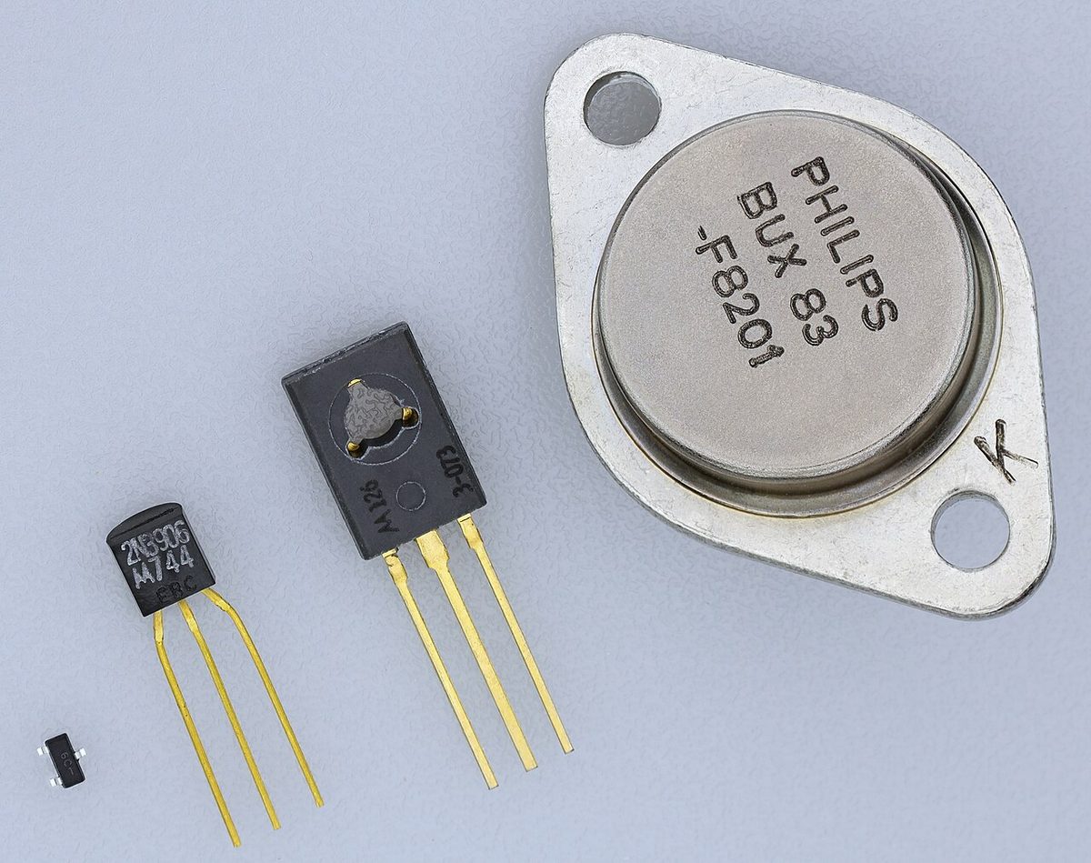
Switching transistors are the basis of digital electronics and of solid-state power devices. A static inverter switches battery DC with transistors to produce 115 V 400 Hz AC with no moving parts, and electronic proximity sensors, which have no contacts to wear, are preferred to microswitches on modern aircraft for detecting the position of parts such as doors and landing gear.
Integrated circuits
An integrated circuit (IC) is a complete circuit, of transistors, diodes, resistors and capacitors, fabricated on a single chip of silicon. Modern ICs contain millions of transistors. Compared with the same circuit built from separate components, an IC is far smaller, lighter, cheaper and more reliable, with fewer soldered joints to fail. Microprocessors, memory chips, amplifiers and logic chips are all integrated circuits, and a single logic IC may contain several gate circuits.
Exam tip: a diode has one PN junction, a bipolar transistor two junctions and three regions, and an IC many devices on a single silicon chip.
Logic gates and truth tables
Digital circuits represent information in binary: every signal is either 1 (true, usually a high voltage) or 0 (false, usually a low voltage). A logic gate is a circuit, built from transistors, with one or more binary inputs and a single binary output determined by a fixed logical rule. A truth table lists the output for every combination of inputs.
The three basic gates are:
- AND gate: the output is 1 only when all inputs are 1. It behaves like switches in series: the lamp lights only if both are closed.
- OR gate: the output is 1 when any one or more inputs is 1, and 0 only when all are 0. It behaves like switches in parallel.
- NOT gate (inverter): a single input, and the output is its opposite, 1 for 0 and 0 for 1. Its symbol is a triangle with a small circle, the inversion bubble, at the output.
Three further gates are derived from them:
- NAND gate (NOT AND): an AND gate followed by an inverter. The output is 0 only when all inputs are 1.
- NOR gate (NOT OR): an OR gate followed by an inverter. The output is 1 only when all inputs are 0.
- Exclusive OR (XOR) gate: for two inputs, the output is 1 only when the inputs differ. Unlike OR, two inputs both at 1 give 0.
| Input A | Input B | AND | OR | NAND | NOR | XOR |
|---|---|---|---|---|---|---|
| 0 | 0 | 0 | 0 | 1 | 1 | 0 |
| 0 | 1 | 0 | 1 | 1 | 0 | 1 |
| 1 | 0 | 0 | 1 | 1 | 0 | 1 |
| 1 | 1 | 1 | 1 | 0 | 0 | 0 |
In the standard symbols the AND gate is D-shaped, with a flat input side and a curved output; the OR gate is shield-shaped, with a curved input side; a bubble at the output of either marks the inverted form, NAND or NOR. NOT combined with AND or OR can produce every other logic function, and NAND or NOR gates alone are each sufficient to build any of them.
Exam tip: AND needs all inputs, OR needs any input, XOR needs the inputs to differ. A bubble inverts: NAND is the exact opposite of AND, NOR of OR.
Aircraft system descriptions are full of this logic, written in words:
- On the A320 the APU generator line contactor closes if the generator's parameters are normal AND the external power contactor is open.
- On the A320 the ram air turbine extends automatically if AC BUS 1 AND AC BUS 2 are both lost with the speed above 100 kt.
- On the A320 the slats retract from the alpha/speed lock only when the angle of attack is below 7.6° AND the speed is above 154 kt.
- On the Boeing 737 the TR UNIT light comes on in flight if TR 1 fails OR if TR 2 AND TR 3 both fail: an AND gate feeding an OR gate.
An XOR gate, whose output flags a difference, can compare two signals that should agree, the kind of check made when one computing channel is monitored against another. Combined in large numbers on integrated circuits, gates form the arithmetic logic units, memories and processors of flight management computers, autopilots and flight control computers, FADEC engine controllers, navigation systems, EFIS and ECAM or EICAS display systems, and the built-in test equipment that monitors them all (see avionics computers and data buses and FADEC and engine fuel control).
Frequently asked questions
What is the difference between forward and reverse bias?
A PN junction is forward biased when the P side is connected to the positive of the supply and the N side to the negative. The applied voltage overcomes the barrier of the depletion region and current flows freely. Reverse the connections and the junction is reverse biased: the depletion region widens and only a tiny leakage current flows. A diode therefore conducts in one direction and blocks in the other.
What is a blocking diode used for on an aircraft?
A blocking diode lets current flow in one direction only and so acts as an electrical non-return valve. It prevents reverse current, for example from the battery back into a failed generator, it lets several sources feed one bus without any of them back-feeding another, and it protects equipment against reversed polarity. The rectifier diodes of an alternator do the same job, which is why an alternator needs no reverse current cut-out.
What does a NAND gate do?
A NAND gate is an AND gate followed by an inverter: its output is 0 only when all of its inputs are 1, and 1 in every other case. For two inputs the truth table is 00 gives 1, 01 gives 1, 10 gives 1 and 11 gives 0. NAND gates are universal: any other logic function, including AND, OR and NOT, can be built from NAND gates alone, which is why they are so widely used in integrated circuits.
What is the difference between an OR gate and an exclusive OR gate?
An OR gate gives an output of 1 when any one or more of its inputs is 1, so two inputs both at 1 give 1. An exclusive OR (XOR) gate gives 1 only when its two inputs differ, and 0 when they are the same, so two inputs both at 1 give 0. Because its output flags a difference, an XOR gate can act as a simple comparator between two signals that should agree.
What are the two main functions of a transistor?
A transistor works as an amplifier or as a switch. As an amplifier, a small current into the base controls a proportionally larger current between collector and emitter, so a weak signal can drive a strong one. As a switch, enough base current turns the transistor fully on and no base current turns it fully off. Switching transistors are the building blocks of logic gates, computers, static inverters and solid-state power control.
Test yourself on Semiconductors and Logic Gates
The v1prep banks cover this topic in Aircraft General Knowledge (021), with a worked explanation for every answer. EASA ATPL, PPL, IR and CPL, the FAA written tests and A320/B737 type ratings.
Start practising →Sources and further reading
- FAA Aviation Maintenance Technician Handbook, General (FAA-H-8083-30B), Electricity and Electronics, semiconductors and logic circuits
- EASA Easy Access Rules for Aircrew (Regulation (EU) No 1178/2011), ATPL and CPL theoretical knowledge learning objectives, subject 021
- EASA, Explanatory Note to ED Decision 2018/001/R, Part-FCL theoretical knowledge learning objectives
- FAA Aviation Maintenance Technician Handbook, Airframe (FAA-H-8083-31B), Aircraft Electrical System
Library articles are written for study and exam preparation. They do not replace your aircraft's approved documentation, your operator's procedures or the regulations themselves.