Transformers, Converters and AC Motors
Transformers change the voltage of an alternating current by mutual induction, rectifiers convert AC to DC and inverters convert DC to AC. With the AC motors that run on the aircraft's three-phase supply, they connect the generators to loads that need a different voltage, a different kind of current or mechanical power.
A transport aeroplane generates three-phase AC at 115/200 V and 400 Hz, yet its loads want many other things: 28 V DC for the DC buses and battery charging, 26 V AC for some instruments, AC from the battery when the generators have failed, and mechanical power for pumps, fans and actuators. A small family of devices bridges the gap. Transformers change AC voltage, rectifiers turn AC into DC, inverters turn DC into AC, and AC motors turn the three-phase supply into rotation.
All of them rest on the principles in electromagnetism and induction and AC electrical theory; rectifiers and static inverters also depend on the diodes and transistors described in semiconductors and logic gates.
Transformer principles and ratios
A transformer is two coils, the primary and the secondary, wound on a common iron core but not electrically connected to each other. An alternating current in the primary sets up an alternating magnetic flux in the core. The flux links the secondary and, by Faraday's law, induces an EMF in it. This is mutual induction. A transformer has no moving parts and is highly efficient; real transformers typically reach 95 to 99 %.
Only a changing flux induces an EMF, so a transformer works on AC but not on steady DC, and it does not change the frequency: 400 Hz in gives 400 Hz out.
The transformation ratio compares the two windings:
- r = N2 / N1 = E2 / E1
where N is the number of turns and E the voltage, 1 for the primary and 2 for the secondary. The voltage per turn is the same in both windings, so the voltages are in the same ratio as the turns.
An ideal transformer delivers all the power it receives, so V1 × I1 = V2 × I2, and the currents are in the inverse ratio. If a primary of 1,000 turns and a secondary of 200 turns give r = 0.2, then 115 V on the primary gives 23 V on the secondary; if the load draws 10 A from the secondary, the primary draws only 2 A. A transformer changes voltage and current in opposite directions; it cannot create power.
The core is made of thin sheets of silicon steel insulated from each other, a laminated core, to keep the eddy currents induced in the iron small. The same weight argument that gives aircraft their 400 Hz supply applies here: for a given voltage, a higher frequency needs less iron, so aircraft transformers are much smaller and lighter than their 50 or 60 Hz equivalents.
Step-up, step-down and autotransformers
A step-up transformer has more turns on the secondary than on the primary (r greater than 1): the secondary voltage is higher and the secondary current correspondingly lower. A step-down transformer has fewer secondary turns (r less than 1): the voltage falls and the available current rises. Every step-up transformer is therefore a current step-down, and vice versa.
An autotransformer has a single winding with a tapping part-way along it. The whole winding serves as the primary and the tapped section as the secondary, or the other way round, so part of the winding carries both currents. It needs less copper and is lighter and cheaper than a two-winding transformer, but it gives no electrical isolation between input and output and cannot be used where isolation is required. The typical aircraft application is stepping 115 V AC down to the 26 V AC used by certain instruments, synchros and resolvers.
Exam tip: turns ratio equals voltage ratio; current ratio is the inverse. A transformer does not work on DC and does not change frequency.
Current transformers
A current transformer (CT) is a step-down transformer for current. Its primary is usually the main power conductor itself, passing through the core as a single turn or a few turns, and its secondary has many turns. The secondary current is a small, manageable fraction of the primary current and proportional to it, so it can drive a meter or a protection circuit without the heavy current ever reaching them.
Generator systems use CTs to measure load and to detect faults. In differential current protection, CTs at both ends of a protected zone compare the current leaving the generator with the current arriving at the bus; a disagreement means current is escaping to a fault and the generator is tripped (see generator control, protection and paralleling). The bus power control unit of a large aircraft monitors the generators and buses through CTs.
Warning: a CT's secondary must never be open-circuited while its primary carries current. With nothing to oppose the primary flux, a dangerously high voltage is induced across the secondary.
Copper and iron losses
A real transformer loses a small part of the power passing through it, as heat, in two ways:
- Copper loss is the I²R heating of the current in the resistance of the primary and secondary windings. It grows with the load current, and since it varies with the square of the current, doubling the load quadruples it.
- Iron loss occurs in the core and has two parts. Eddy current loss comes from the currents that the alternating flux induces in the iron itself, and is reduced by laminating the core. Hysteresis loss is the energy used in magnetising the core back and forth every cycle, and is reduced by choosing a core material, such as silicon steel, with a narrow hysteresis loop.
The same losses occur in motors and generators, which is why their cores are laminated too.
Rectifiers: AC to DC
A rectifier converts AC into DC by allowing current to flow in one direction only, using semiconductor diodes as one-way valves.
- A half-wave rectifier uses a single diode and passes only one half of each cycle, wasting the other.
- A full-wave rectifier passes both halves, turning the negative half-cycles positive. A bridge of four diodes does this for a single-phase supply, and a bridge of six diodes for a three-phase supply.
The output is pulsating DC, which a capacitor can smooth.
A transformer rectifier unit (TRU), often called simply a TR, combines a step-down transformer with a rectifier to produce 28 V DC from the 115 V AC supply. On AC-generating aircraft the TRUs are the normal source of DC. The Boeing 737 has three TRs fed from its AC transfer buses; TR 3 powers the battery bus and backs up TR 1 and TR 2. The A320 has TR 1 and TR 2, an essential TR that can supply the DC essential bus from the AC essential bus, and on aircraft so fitted a fourth TR dedicated to the DC entertainment bus. A TRU fails with the AC that feeds it, so when no AC source remains the essential DC bus falls back on the battery.
Rectifiers appear inside machines as well. A light aircraft's alternator produces AC that built-in diodes rectify for the 14 V or 28 V bus, the diodes also blocking reverse current from the battery; and a brushless alternator feeds its main field through a rotating rectifier on the shaft (see AC generators, CSD and IDG).
Static and rotary inverters
An inverter converts DC into AC. On aircraft whose main supply is constant-frequency AC, its chief use is as the emergency AC source: when the generators have failed, the battery feeds the inverter, which supplies 115 V 400 Hz to the essential AC loads such as instruments and radios.
- A rotary inverter does the job mechanically: a DC motor drives an AC generator. It has the brushes, bearings and wear of any rotating machine.
- A static inverter does it electronically, switching the DC with transistors to build an AC waveform. "Static" means it has no moving parts, so there are no brushes or bearings to wear, and modern inverters are of this type.
On the A320 the static inverter is a single-phase unit of 1 kVA, fed from battery 1; after a total loss of generation it supplies the AC static inverter bus and, above 50 kt, the AC essential bus until the emergency generator comes on line or whenever that generator is unavailable. On the Boeing 737 the static inverter, fed by the batteries, powers the AC standby bus when all normal AC is lost. The time it can do so is limited by the battery; see aircraft batteries.
A rectifier followed by an inverter makes a frequency converter. Variable speed constant frequency (VSCF) systems use exactly this to turn the frequency-wild output of a directly driven generator into constant 400 Hz power.
Rotating magnetic fields
When three-phase AC is fed to three stator windings spaced 120° apart, the three fields reach their peaks one after another, and their sum is a field of constant strength that rotates around the stator. This rotating magnetic field is what makes simple AC motors possible: whatever the rotor, the field drags it round.
The field turns at the synchronous speed, fixed by the supply frequency and the number of poles:
- synchronous speed (rpm) = 120 × f / number of poles.
A four-pole winding on a 400 Hz supply gives 120 × 400 / 4 = 12,000 rpm.
The direction of rotation follows the phase sequence. Swapping any two of the three supply connections reverses the sequence, the rotating field and the motor. That is why an external power supply with an incorrect phase sequence is rejected by the aircraft: it would run three-phase motors backwards.
Induction and synchronous motors
The two main types of AC motor on aircraft differ in how the rotor becomes magnetic.
In an induction motor the rotor has no electrical connection at all. The rotating stator field sweeps across the rotor conductors and induces currents in them by mutual induction; those currents set up the rotor's own field, which is dragged round after the stator's. The usual rotor is the squirrel-cage rotor: conducting bars in slots along a laminated iron cylinder, short-circuited by a ring at each end so that they form a closed cage. With no brushes, slip rings or commutator, the induction motor is simple, robust, cheap and reliable, and it is the most common AC motor in aircraft as elsewhere.
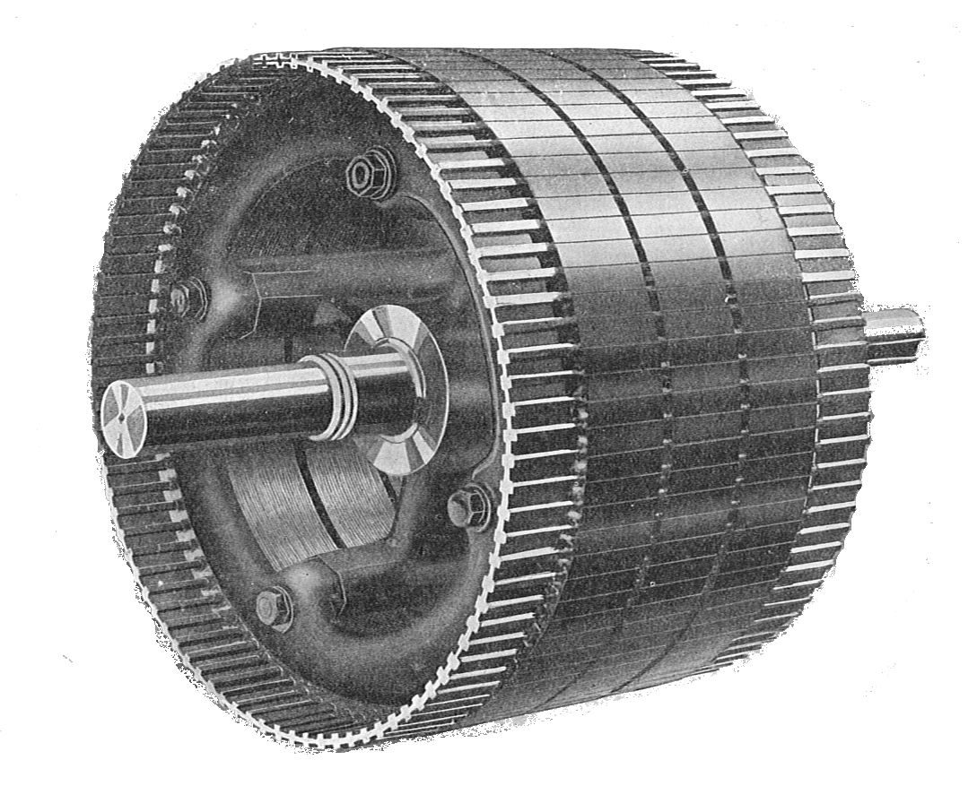
An induction motor always turns slightly slower than the field. If the rotor ever reached synchronous speed, the field would no longer cut the rotor bars, no current would be induced and there would be no torque. The difference is the slip, (synchronous speed − rotor speed) / synchronous speed, which is 1 at standstill and typically a few per cent in normal running.
In a synchronous motor the rotor is supplied with DC, usually through slip rings, making it an electromagnet: in effect a rotating-field alternator run as a motor. The rotor locks onto the rotating stator field and turns at exactly synchronous speed, with no slip, whatever the load within its capacity. It suits applications that need a constant speed set by the supply frequency.
| Induction motor | Synchronous motor | |
|---|---|---|
| Rotor | Squirrel cage, no connections | DC-fed field winding, slip rings |
| Speed | Slightly below synchronous (slip) | Exactly synchronous |
| Construction | Simplest, most robust | More complex |
| Typical use | Most aircraft AC motors | Constant-speed applications |
Single-phasing of motors
A three-phase motor depends on all three phases for its rotating field. If one phase of the supply fails, a fault called single-phasing, a motor that is already running keeps turning on the pulsating field of the remaining supply, but with reduced torque and a greatly increased current in the remaining lines. It overheats and its windings can be damaged, and it stalls if the load exceeds the reduced torque. A stopped motor cannot restart at all, because a single phase produces no rotating field.
Protection relays detect single-phasing and isolate the motor. For the crew the lesson is that an AC motor-driven service can fail or trip off without any fault in the motor itself, because of a problem upstream in the supply; its bus and circuit protection are the first things to check. How the buses feeding these devices are arranged is described in electrical power distribution.
Frequently asked questions
What is the transformation ratio of a transformer?
The transformation ratio is the ratio of secondary to primary turns, which equals the ratio of secondary to primary voltage: r = N2 / N1 = E2 / E1. A ratio above 1 steps the voltage up, below 1 steps it down. Because an ideal transformer delivers the power it receives, the currents change in the inverse ratio: a transformer that steps the voltage down five times steps the current up five times. The frequency is unchanged.
What is a transformer rectifier unit (TRU)?
A transformer rectifier unit converts the aircraft's 115 V 400 Hz three-phase AC into 28 V DC. A transformer first steps the voltage down, then a bridge of semiconductor diodes rectifies it into direct current for the DC buses and battery charging. The Boeing 737 has three TRs fed from its AC transfer buses; the A320 has TR 1, TR 2 and an essential TR, plus, on aircraft so fitted, a fourth TR for the DC entertainment bus.
What is the difference between a static inverter and a rotary inverter?
Both convert DC into AC. A rotary inverter does it mechanically: a DC motor turns an AC generator. A static inverter does it electronically with transistors and has no moving parts, so there are no brushes or bearings to wear. On modern transport aircraft a battery-fed static inverter supplies essential AC when the generators have failed: on the A320 a 1 kVA single-phase unit, on the 737 the source of the AC standby bus.
What happens if one phase is lost to a three-phase induction motor?
This is single-phasing. A running motor keeps turning on the pulsating field of the remaining supply, but with reduced torque and a greatly increased current in the remaining lines, so it overheats and its windings can be damaged. It stalls if the load exceeds the reduced torque, and it cannot start from rest, because a single phase produces no rotating field. Protection relays detect the condition and isolate the motor.
Why must a current transformer never be open-circuited?
A current transformer steps a large current down to a small, proportional one for measurement or protection. Its primary is the main conductor, carrying the full load current whatever the secondary does. With the secondary connected, its current opposes the primary flux. If the secondary is opened while the primary carries current, nothing opposes that flux and a dangerously high voltage is induced across the many secondary turns.
Test yourself on Transformers, Converters and AC Motors
The v1prep banks cover this topic in Aircraft General Knowledge (021), with a worked explanation for every answer. EASA ATPL, PPL, IR and CPL, the FAA written tests and A320/B737 type ratings.
Start practising →Sources and further reading
- FAA Aviation Maintenance Technician Handbooks, General (FAA-H-8083-30B) and Airframe (FAA-H-8083-31B), alternating current, electronics and aircraft electrical systems
- FAA Aviation Maintenance Technician Handbook, Airframe (FAA-H-8083-31B), Aircraft Electrical System
- EASA Easy Access Rules for Large Aeroplanes (CS-25), CS 25.1351 to 25.1365, electrical systems and equipment
- EASA Easy Access Rules for Aircrew (Regulation (EU) No 1178/2011), ATPL and CPL theoretical knowledge learning objectives, subject 021
Library articles are written for study and exam preparation. They do not replace your aircraft's approved documentation, your operator's procedures or the regulations themselves.