Electrical Fundamentals and DC Circuits
Electricity in an aircraft circuit is a flow of electric charge, driven by an electromotive force and opposed by resistance. In a direct current (DC) circuit the charge flows in one direction only, and Ohm's law, the power formula and Kirchhoff's laws describe how voltage, current and power are shared around the circuit.
Every electrical system in an aircraft, from the 14 V bus of a light single to the 28 V DC and 115 V AC networks of an airliner, obeys the same few laws. A pilot needs them to read a voltmeter or an ammeter correctly, to understand why a circuit breaker trips and why it may be reset only once, and to see why larger aircraft use higher voltages.
This article covers direct current (DC) circuits: the quantities, Ohm's law, power, series and parallel connection, Kirchhoff's laws, capacitors and inductors, faults and measurement. Alternating current is covered in AC electrical theory, and the magnetic effects of current in electromagnetism and induction.
Current, voltage and EMF
Electric charge is carried in metal conductors by electrons, and its unit is the coulomb. Electric current is the rate at which charge flows past a point. Its unit is the ampere (A): 1 A is a flow of 1 coulomb per second. Direct current (DC) flows in one direction only; alternating current reverses its direction periodically.
Electrons, being negative, flow from the negative terminal of a source round the circuit to the positive terminal. By an older convention, conventional current is taken to flow the other way, from positive to negative. EASA exam texts use conventional current, including in the rules for magnetic effects such as the right-hand grasp rule for a solenoid. The choice of direction changes no result as long as it is applied consistently.
The electromotive force (EMF) is the driving force produced by a source, such as a battery or generator, that makes charge flow. The potential difference (PD) is the voltage between any two points of a circuit, for example across a load. Both are measured in volts (V). Under load a source delivers less than its EMF, because part of it is used in the source's internal resistance: a fully charged lead-acid cell gives about 2.2 V off load but about 2.0 V on load, and a nickel-cadmium cell about 1.2 V on load. Cells in series add their voltages, so twelve lead-acid or twenty nickel-cadmium cells make a 24 V battery; cells in parallel add their capacity in ampere-hours at the voltage of one cell.
Light aircraft use 14 V systems with 12 V batteries, larger aircraft 28 V systems with 24 V batteries. The bus is held a couple of volts above the battery, because charging current flows into the battery only if the bus is at a higher potential.
Current flowing in a conductor always has three effects: heating, used in lamps and fuses; magnetic, used in motors, generators, relays and transformers; and chemical, used in charging batteries.
Resistance and Ohm's law
Electrical resistance is the opposition a material offers to current. Its unit is the ohm (Ω): a conductor has a resistance of 1 Ω if 1 V across it drives a current of 1 A. Larger values are given in kilohms (kΩ, 1,000 Ω) and megohms (MΩ, 10⁶ Ω). The resistance of a conductor depends on its material, its length, its cross-sectional area and its temperature: a longer wire has more resistance, a thicker one less, which is why cables carrying heavy currents are thick.
Ohm's law states that the voltage across a resistance equals the current through it times the resistance:
- V = I × R, so I = V / R and R = V / I.
A 24 V supply across a 6 Ω resistor drives I = 24 / 6 = 4 A. The traps in exam questions are to multiply (144) or to invert the division (0.25).
Electrical power
Electrical power is the rate at which energy is converted, measured in watts (W); 1 W is 1 joule per second. For a DC circuit:
- P = V × I, and, substituting Ohm's law, P = I² × R and P = V² / R.
A 24 V circuit carrying 5 A converts 24 × 5 = 120 W. Because heating rises with the square of the current, doubling the current in a wire quadruples the heat produced in it. That is how a fuse works, and why every circuit is protected against excess current. It is also why larger aircraft use 28 V: the same power at twice the voltage needs half the current, so conductors can be thinner and lighter and wiring losses are lower.
Series and parallel circuits
In a series circuit the components are connected end to end, so the same current flows through each and the voltages across them add up to the supply voltage. The total resistance is the sum of the individual ones, R = R1 + R2 + R3: three 10 Ω resistors in series make 30 Ω. A single break stops current everywhere.
In a parallel circuit the components are connected across the same two points, so each has the same voltage and the branch currents add. The total resistance is found from 1/R = 1/R1 + 1/R2 + 1/R3, and it is always less than the smallest branch: three 60 Ω resistors in parallel make 20 Ω. For two resistors the shortcut is product over sum, R1 × R2 / (R1 + R2). Adding a branch lowers the total resistance and increases the total current.
| Series | Parallel | |
|---|---|---|
| Current | Same through every component | Divides between branches, branch currents add |
| Voltage | Divides, the drops add to the supply | Same across every branch |
| Total resistance | Sum of all resistances | Less than the smallest branch |
| One component open | Whole circuit stops | Other branches keep working |
Take a 28 V supply with 4 Ω and 10 Ω. In series they make 14 Ω, the current is 2 A, and the drops are 8 V and 20 V. In parallel each has the full 28 V, so they take 7 A and 2.8 A, a total of 9.8 A.
Aircraft loads are connected in parallel. A bus bar is a heavy copper conductor fed by the generators, battery or external power, and each service takes its supply from it through its own circuit breaker and switch, so every load receives full bus voltage and one failure does not stop the others. In a metal aircraft only the positive wire runs to each load: the negative side of the sources and loads is connected to the airframe, which forms the return path. Bonding keeps all metal parts at the same potential. Aircraft built of non-conducting composites need a return wire as well.
Kirchhoff's laws
Kirchhoff's current law (KCL), his first law, states that the total current flowing into any junction equals the total current flowing out, because charge cannot accumulate at a point. A bus feeding loads of 5 A, 10 A and 15 A must itself be supplied with 30 A.
Kirchhoff's voltage law (KVL), his second law, states that around any closed loop the sum of the voltage drops equals the sum of the EMFs applied; put another way, the algebraic sum of the voltages round the loop is zero. It expresses the conservation of energy. In the series example above, 8 V plus 20 V equals the 28 V supply.
Exam tip: series circuits share voltage, parallel circuits share current. KCL is about currents at a junction (charge conservation), KVL about voltages round a loop (energy conservation).
Capacitors and inductors
A capacitor is two conducting plates separated by an insulator, the dielectric. A voltage applied across it moves charge onto the plates, and current flows only while the capacitor charges or discharges; once charged, it blocks steady direct current. Capacitance is measured in farads (F): a capacitance of 1 F stores 1 coulomb of charge with 1 V across the plates, and practical values are microfarads or smaller. Capacitances in parallel add, while capacitances in series combine in the same way as resistances in parallel. In an AC circuit with pure capacitance, current leads voltage by 90°. Aircraft uses include smoothing the output of rectifiers, capacitance probes that measure fuel quantity, as in the A320's tanks, and capacitive proximity sensors.
An inductor is a coil of wire, often wound on an iron core. Current through it builds a magnetic field, and any change of current induces an EMF that opposes the change, so an inductor resists changes of current while offering only its wire resistance to a steady one. Inductance is measured in henries (H) and increases with the number of turns and with an iron core. In an AC circuit with pure inductance, current lags voltage by 90°. The memory aid is CIVIL: in a capacitor (C), I leads V; V leads I in an inductor (L). Relays, solenoids, motors and transformers all depend on inductance; see electromagnetism and induction.
Open circuits and short circuits
An open circuit is a break in the conducting path, such as a broken wire, a blown fuse, a failed switch or a loose connection. No current flows and the load stops working, but no excess current flows either. A short circuit is an unintended low-resistance path that bypasses the load, often a conductor touching another or touching earth. The current then rises to a level limited only by the source and the wiring, and the wiring can overheat, melt and start a fire.
Fuses, circuit breakers and current limiters are connected in series with the load and rated to open the circuit before the wiring overheats: they protect the circuit, above all its wiring. CS 25.1357 and 14 CFR 25.1357 require resettable breakers on large aeroplanes to be trip-free, opening on a fault whatever the position of their control, so a breaker cannot be held in against a fault. The accepted rule is one reset only, after a cooling period and only if the service is needed; never after smoke or a burning smell. A blown fuse is replaced once, never by a higher rating; if it blows again the fault must be found. See circuit protection and switching devices.
In a series circuit with an open, a voltmeter across the failed component reads the full supply voltage, while across each good component it reads zero, because no current flows to cause a drop; an ohmmeter across the open component shows infinite resistance.
Measuring voltage and current
A voltmeter is connected in parallel, across the two points being measured, without breaking the circuit. Its very high internal resistance means it draws negligible current and does not disturb the circuit. An ammeter is connected in series, so that the whole current passes through it, and has a very low resistance. Connected across a supply by mistake, an ammeter would act almost as a short circuit.
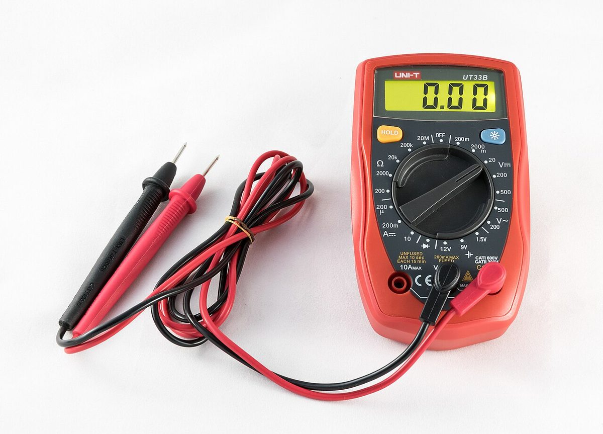
On the flight deck, a bus voltmeter reading about 14 V in a 12 V system, or about 28 V in a 24 V system, is normal: it shows the generator charging the battery. A centre-zero battery ammeter shows current into the battery (charge, right of zero) or out of it (discharge, left of zero); a high charge just after engine start that tapers off is normal. A loadmeter is wired into a generator or alternator output, reads only positive values and shows the total load it carries. On the A320 the crew check battery voltage with the BAT pushbuttons OFF: above 25.5 V shows a charge above 50 %, and at or below 25.5 V a charging cycle of about 20 minutes is needed.
Frequently asked questions
What is Ohm's law?
Ohm's law states that the voltage across a resistance equals the current through it multiplied by the resistance: V = I × R. It can be rearranged as I = V / R and R = V / I, so any one quantity can be found from the other two. For example, a 24 V supply across a 6 ohm resistor drives a current of 4 A. Multiplying 24 by 6 or dividing 6 by 24 are the usual exam traps.
What is the difference between EMF and potential difference?
Electromotive force (EMF) is the driving force produced by a source such as a battery or generator, the force that makes charge flow around the circuit. Potential difference (PD) is the voltage between any two points in a circuit, for example across a lamp or a resistor. Both are measured in volts. Under load a source's terminal voltage is less than its EMF, because part of the EMF is used in the source's own internal resistance.
How is a voltmeter connected, and why?
A voltmeter is connected in parallel, across the two points whose potential difference is to be measured, without breaking the circuit. It has a very high internal resistance, so it draws almost no current and does not disturb the circuit it is measuring. An ammeter is the opposite: it is connected in series so that the whole current flows through it, and it has a very low resistance so that it does not restrict that current.
What is the difference between a short circuit and an open circuit?
An open circuit is a break in the conducting path, such as a broken wire, a blown fuse or a failed switch: no current flows and the load stops working, but nothing overheats. A short circuit is an unintended low-resistance path that bypasses the load, such as a bare wire touching structure. The current then rises to a level limited only by the source and the wiring, which can melt insulation and start a fire.
Why do larger aircraft use 28 V DC systems rather than 14 V?
Power equals voltage times current, so a load taking a given power at 28 V draws only half the current it would need at 14 V. Lower current allows conductors with a smaller cross-section, which saves weight, and reduces the losses in the wiring. Light aircraft therefore use 14 V systems with 12 V batteries, while larger aircraft use 28 V systems with 24 V batteries, the bus in each case being held above battery voltage so that the battery charges.
What does Kirchhoff's current law state?
Kirchhoff's current law, his first law, states that the total current flowing into any junction in a circuit equals the total current flowing out of it, because charge cannot accumulate at a point. If a bus bar feeds three loads taking 5 A, 10 A and 15 A, the feeder supplying that bus must carry 30 A. His second law, the voltage law, states that the voltage drops around any closed loop add up to the EMF applied to it.
Test yourself on Electrical Fundamentals and DC Circuits
The v1prep banks cover this topic in Aircraft General Knowledge (021), with a worked explanation for every answer. EASA ATPL, PPL, IR and CPL, the FAA written tests and A320/B737 type ratings.
Start practising →Sources and further reading
- FAA Aviation Maintenance Technician Handbook, General (FAA-H-8083-30), Electricity
- FAA Pilot's Handbook of Aeronautical Knowledge (FAA-H-8083-25), Chapter 7, Aircraft Systems
- EASA Easy Access Rules for Aircrew (Part-FCL), theoretical knowledge syllabus, 021 Airframe, Systems, Electrics, Power Plant
- EASA Easy Access Rules for Large Aeroplanes (CS-25), CS 25.1357 Circuit protective devices
- 14 CFR 25.1357, Circuit protective devices
Library articles are written for study and exam preparation. They do not replace your aircraft's approved documentation, your operator's procedures or the regulations themselves.