Avionics Computers and Data Buses
Avionics computers are the digital processors that turn sensor inputs into displays, warnings and control commands on an aircraft. They combine a central processing unit, memory and input and output conversion, run certified software, test themselves and exchange data over standard data buses such as ARINC 429 and AFDX.
A modern airliner carries dozens of computers. The air data computer, the inertial reference units, the flight management and flight control computers, the display processors and the engine controls all take in sensor signals, compute and pass the results to other systems. Pilots rarely see them, but their structure explains much of what appears on the flight deck: why a display shows a flag instead of a wrong value, why a unit takes time to test itself after power-up, and why one failed sensor can affect several systems at once.
This article covers the computing basics examined in ATPL instrumentation theory: analogue and digital computers, the processor, memory, conversion between analogue and digital signals, software, built-in test and the data buses that link the units. Individual systems are described in articles such as air data computer, flight management system and fly-by-wire.
Analogue and digital computers
An analogue computer represents quantities by continuously variable physical values: voltages, pressures or the rotation of a shaft. The analogue air data computers of older jets worked this way, with pressure transducers, two-phase servomotors driving shafts, and CX synchros transmitting shaft positions, arranged in modules for altitude, airspeed, Mach number, true airspeed and rate of climb. Analogue computing is now largely obsolete in aircraft.
A digital computer represents everything as binary numbers, built from bits that are either 0 or 1. It has four parts:
- input devices, which on an aircraft are sensors and other computers, such as the radio altimeter, air data and fuel flow;
- the central processing unit (CPU), which processes the data;
- memory, which stores the program and the data;
- output devices, such as the display symbol generators and the control display unit of the flight management system.
Digital computers are far less affected by the drift and noise of analogue circuits, compute complex formulas precisely, test themselves more thoroughly, connect easily to digital data buses and can be changed by loading new software rather than rebuilding hardware. All current production transport aeroplanes use them.
CPU and ALU
The CPU has three main elements:
- the arithmetic logic unit (ALU), which performs arithmetic and logical operations on binary numbers;
- registers, small fast temporary stores, among them the accumulator that holds the value being worked on;
- the control unit, which fetches and decodes the program's instructions and times every operation with pulses from a crystal-controlled clock.
The ALU is built from logic gates, circuits with binary inputs and one binary output such as AND, OR, NOT, NAND, NOR and exclusive-OR, of which a single integrated circuit can contain millions (see semiconductors and logic gates). A shift register is a register whose bits move one position along at each clock pulse. Shifting a binary number one place to the left doubles it, and shifting bits out one at a time turns a parallel word into the serial stream that a data bus carries, or back again at the receiver.
Memory types: RAM and ROM
| Memory | Written | Erased | Volatile? | Typical use |
|---|---|---|---|---|
| RAM (random access memory) | Continuously, by the program | Overwritten at will | Yes | Working data and partial results |
| ROM (read-only memory) | By the manufacturer | Cannot be | No | Fixed programs |
| PROM (programmable ROM) | Once, after manufacture | Cannot be | No | Programs set once |
| EPROM (erasable PROM) | With a programming device | By ultraviolet light | No | Programs changed occasionally |
| EEPROM (electrically erasable PROM) | Electrically, in place | Electrically | No | Settings and small data sets |
| Flash memory | Electrically | Electrically | No | Software, databases, recorded data |
RAM is needed wherever data or instructions must be written, read and altered at will, and it is normally volatile memory: its contents are lost when power is removed. Anything that must survive a power interruption is kept in non-volatile memory. Flash memory is fast and can be rewritten many times, which suits data that must be updated regularly, such as a flight management computer's navigation database, replaced every 28-day AIRAC cycle.
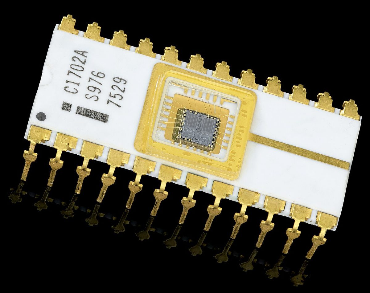
A configuration module is a small non-volatile memory that belongs to the airframe rather than to the computer. An air data computer's module holds the aircraft's probe positions and pressure-gathering coefficients, which the computer uses for the position error correction. A generic computer can therefore be fitted to different types, and a replacement unit reads the same module without recalibration.
A/D and D/A conversion
Most sensors are analogue: pressure transducers, thermocouples, position potentiometers and AC tachometer generators produce continuously varying voltages. Analogue-to-digital (A/D) conversion samples such a signal at a high rate and turns each sample into a binary number. The resolution of the converter, in bits, sets the smallest step it can distinguish: an 8-bit converter divides its range into 256 levels, a 12-bit converter into 4,096. The sampling rate sets how quickly it follows a changing signal. Digital-to-analogue (D/A) conversion is the reverse, used when a computer must drive an analogue indicator or a servo motor.
ATPL texts call the layer that performs these conversions the basic input output system (BIOS): it converts input signals into a form the computer can work with and converts outputs into a form the operator or another system can use. In personal computers the same abbreviation names the start-up firmware.
Some data are digital from the start. An encoding altimeter, for example, reports altitude to the transponder in a Gillham code in 100 ft steps, always referenced to 1013.25 hPa.
Software and programming languages
The CPU executes machine code, binary instructions specific to its design. Assembly language writes those instructions as short symbolic names; it is defined by the processor's manufacturer and tied to one type of CPU. A high-level programming language, such as FORTRAN, ALGOL, BASIC, C++ or Ada, is independent of any particular computer and easier for its author to read; a compiler translates it into machine code. Avionics software is typically written in such languages under a rigorous development process.
That process is set by EUROCAE ED-12 / RTCA DO-178, which EASA and the FAA accept for airborne software. It assigns each program a software level according to the worst effect its failure could have:
| Level | Failure condition |
|---|---|
| A | Catastrophic: prevents continued safe flight and landing |
| B | Hazardous |
| C | Major |
| D | Minor |
| E | No effect on safety |
Flight control software is level A and needs the most rigorous development and verification. Because identical software could fail identically, critical systems also use dissimilar redundancy: the A320's two ELACs and three SECs come from different suppliers and use different microprocessors, while the Boeing 777 has three primary flight computers, each with three computing lanes.
Built-in test equipment
Every avionics unit tests itself with built-in test equipment (BITE). The ATPL textbooks describe three forms, using the air data computer as the example:
- Power-up BITE runs when the unit is switched on or after a power interruption and checks the processor, the memory and the main functions.
- Continuous BITE checks the inputs and outputs automatically, about once a second, throughout operation.
- Maintenance BITE is started on the ground by an engineer, often with a test or history function that recalls stored faults.
The results reach the crew as flags and alerts. An electronic display shows an amber flag in place of a parameter whose source has failed rather than a wrong value, and the crew selects an alternate source or uses the standby instruments. Maintenance data are kept for the ground: the Boeing 737's MAINT BITE INDEX page on the CDU is available only on the ground. Power-up tests take time, and on the Embraer E190-E2 the aircraft must not be moved during the electrical power-up built-in test, which takes about 2 minutes.
ARINC 429 and AFDX buses
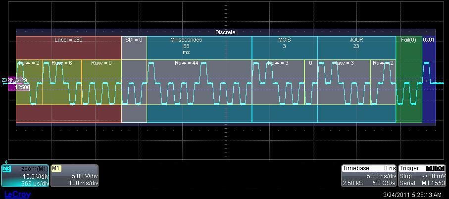
Wiring every parameter separately between every unit would weigh too much, so avionics exchange data over serial data buses. ARINC 429 is the most widely used civil standard, and the bus on which a digital air data computer most commonly sends its outputs.
- It is unidirectional: each bus has a single transmitter, and the receiving units only listen. A unit receiving data from several sources needs an input bus from each, and two units that exchange data in both directions need two buses.
- The standard fixes the format of the data words and assigns the labels that identify the parameter each word carries, such as pressure altitude, together with status information that tells the receiver whether the data are valid.
The Boeing 777 uses ARINC 629, a multi-transmitter bus on which many units take turns to transmit on the same bus.
Avionics Full-Duplex Switched Ethernet (AFDX), standardised as ARINC 664 Part 7, applies Ethernet to aircraft. Units are connected through switches, and each data flow travels on a virtual link, a fixed logical path with reserved bandwidth, so the network is deterministic, as flight-critical data require. The network itself is duplicated for redundancy. AFDX was introduced on the Airbus A380, and the Boeing 787 also uses a network based on ARINC 664.
| Feature | ARINC 429 | AFDX (ARINC 664 Part 7) |
|---|---|---|
| Topology | One transmitter per bus, receivers listening | Switched network |
| Direction | One way | Full duplex |
| Data paths | A separate bus for each source | Virtual links through the switches |
Exam tip: ARINC 429 is one-way, with a single transmitter on each bus and data words identified by a label. AFDX (ARINC 664 Part 7) is full-duplex switched Ethernet with virtual links and a duplicated network.
Because data now travel between units, a single failed source can reach many displays at once. The same design also makes it possible to switch a display to another source, to record large numbers of parameters in the flight recorders and to monitor the aircraft's systems from the ground.
Frequently asked questions
What is the difference between volatile and non-volatile memory?
Volatile memory loses its contents when power is removed. RAM is the typical example: fast to read and write, it holds the working data and partial results of a running program. Non-volatile memory keeps its contents without power. ROM, PROM, EPROM, EEPROM and flash memory are all non-volatile, which is why they hold the programs, the configuration data and the navigation databases that an avionics computer needs when it is switched on.
Why do aircraft computers need analogue-to-digital conversion?
Many aircraft sensors are analogue: pressure transducers, thermocouples, position potentiometers and tachometer generators produce continuously varying voltages. A digital computer can process only binary numbers, so an analogue-to-digital converter samples each signal at a high rate and turns every sample into a binary value. Its resolution in bits and its sampling rate set the accuracy. A digital-to-analogue converter does the reverse to drive analogue indicators and servo motors.
What is ARINC 429?
ARINC 429 is the most widely used digital data bus standard in civil aircraft. Each bus carries data in one direction only, from a single transmitter to the units that listen to it, so two units that exchange data in both directions need two buses. The standard fixes the format of the data words, in which a label identifies the parameter carried, and the status information that goes with them.
What is AFDX?
Avionics Full-Duplex Switched Ethernet, standardised as ARINC 664 Part 7, is an aircraft data network based on Ethernet. Units are connected to switches rather than wired point to point, and each data flow travels on a virtual link with reserved bandwidth, so the network behaves deterministically. The network is duplicated for redundancy. AFDX was introduced on the Airbus A380, and the Boeing 787 also uses a network based on ARINC 664.
What is BITE in an aircraft computer?
Built-in test equipment is the self-test capability of an avionics unit. Textbooks describe three forms: a power-up test of the processor, memory and main functions when the unit is switched on; a continuous test of inputs and outputs, about once a second, throughout operation; and a maintenance test started on the ground by an engineer. Failures appear as flags, crew alerts or maintenance messages.
Test yourself on Avionics Computers and Data Buses
The v1prep banks cover this topic in Instrumentation (022), with a worked explanation for every answer. EASA ATPL, PPL, IR and CPL, the FAA written tests and A320/B737 type ratings.
Start practising →Sources and further reading
- EASA, Explanatory Note to ED Decision 2018/001/R, Part-FCL theoretical knowledge learning objectives (022 Instrumentation)
- FAA Aviation Maintenance Technician Handbook, Airframe (FAA-H-8083-31), Aircraft Instrument Systems, Communication and Navigation
- FAA AC 20-115D, Airborne Software Development Assurance Using EUROCAE ED-12( ) and RTCA DO-178( )
- FAA Instrument Flying Handbook (FAA-H-8083-15B), Chapter 5, Flight Instruments
- FAA, Data Network Evaluation Criteria Handbook (DOT/FAA/AR-09/24), covering ARINC 429, ARINC 629 and ARINC 664
Library articles are written for study and exam preparation. They do not replace your aircraft's approved documentation, your operator's procedures or the regulations themselves.