Propeller Ice Protection
Propeller ice protection keeps ice off the blades, either with electrically heated overshoes on the blade leading edges, switched on in timed cycles so that the ice is loosened and thrown off, or with a freezing point depressant fluid fed to the blades from a slinger ring on the hub.
A propeller blade is a small, fast-moving wing: in icing conditions it collects ice like one, and can do so sooner than the main wing. Ice spoils the blade's aerofoil, costs thrust and, because it rarely forms or breaks away evenly, unbalances a heavy rotating assembly bolted to the front of the engine. Propeller ice protection prevents or removes that ice, and the FAA's approval for flight into known icing requires it.
Two methods are used. Electrothermal propeller de-icing bonds heater overshoes to the blade leading edges and heats them in timed cycles; fluid anti-icing feeds a freezing point depressant to the blades through a slinger ring on the hub. ATPL texts note that most modern installations are electrical. How a propeller works and is controlled is covered in propellers and propeller control; the wing and tail systems of the same aircraft are in de-icing boots and fluid ice protection.
Propeller icing hazards
Small objects collect ice faster than large ones. The share of droplets that actually strike an object, its catch rate efficiency, rises with airspeed and falls as the object's radius increases, and a blade's leading edge is thin and moving fast (see airframe icing). The same depth of ice is also a larger fraction of a thin section than of a thick wing.
The effects follow:
- Loss of efficiency. Ice distorts the aerofoil section of each blade, so the propeller produces less thrust for the same engine power.
- Imbalance and vibration. Ice rarely forms evenly on every blade, and pieces break off one blade before another. The resulting imbalance causes vibration, which can be severe and damaging at high rotational speed.
- Ice impact. Shed ice leaves the blades at high speed and can strike and damage the fuselage near the plane of the propeller.
The spinner and the area around the hub also gather ice. ATPL texts list the spinner among the engine areas that may need protection, and the FAA names the spinner, with the windscreen and the outside air temperature probe, as a good place to look for the first ice. Ice spreading farther back than usual on an unheated spinner is one of the cues of supercooled large droplets, which call for leaving the conditions at once.
Electrothermal overshoes
The usual system bonds a heater overshoe, also called a propeller de-ice boot, to the leading edge of each blade. In the construction ATPL texts describe, the heating element wires are interwoven with glass threads to form a glass cloth, which is cemented between sheets of rubber, with a protective guard of wire gauze beneath the outer rubber covering against impact damage. The overshoe is shaped to fit around the leading edge and cemented in place; some are set into a rebate machined in the blade so that they lie flush with its surface. On many installations the heaters cover the inboard part of each blade, and the outline of the element can often be seen through the rubber.
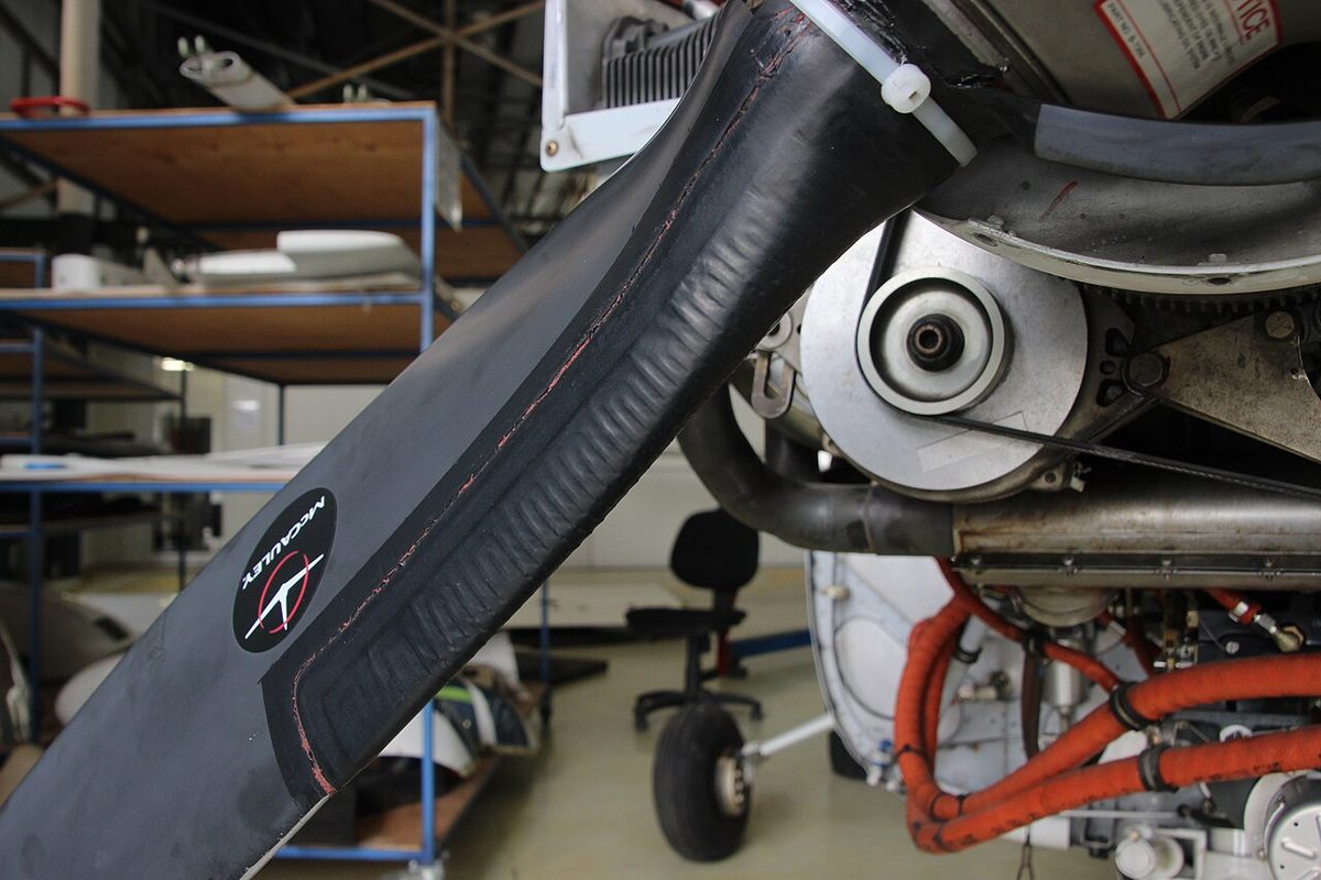
Getting current into a rotating propeller needs a rotating joint. Slip rings are mounted at the rear of the propeller hub, or on the starter ring gear in some designs, and brushes held in a brush block on the stationary engine front casing bear on them, so contact is kept as the propeller turns. The supply may be three-phase alternating current or direct current, and the cables to the blades are long enough to allow for the change of blade pitch. A timer unit decides which elements receive power and when.
Heater elements are purely resistive loads, which work equally well whatever the frequency of the supply. ATPL texts therefore give them as a typical use for a frequency-wild alternator, driven directly from the engine gearbox so that its frequency varies with engine speed; such alternators cannot be paralleled, but a heater does not need them to be (see AC generators, CSD and IDG).
The same technique heats other parts of a turboprop. Engine air intakes are often protected by electrical heater mats, and a single mat can combine continuously heated strips, which anti-ice the areas where ice must never form, with intermittently heated areas switched by a cyclic time switch, which de-ice the rest (see thermal anti-icing).
Fluid systems and slinger rings
The alternative is a fluid system. A slinger ring, a channel mounted on the back of the propeller hub, receives freezing point depressant fluid, glycol-based, pumped through a delivery pipe from a supply tank. Centrifugal force carries the fluid outwards to each blade. Where the blades have rubber overshoes with a trough and longitudinal grooves, the fluid feeds from the slinger ring into the trough and flows out along the grooves; without overshoes, it is piped to each blade root and spreads along the blade by centrifugal action.
The supply comes from an electrically driven pump, whose speed may be varied by a rheostat to control the flow, at about 10 psi; some systems use air pressure instead, with a relief valve and a control valve in the line. Check valves keep the fluid from draining away when the pump is stopped, and the pump has its own filter. Because the fluid stops ice from forming or sticking, this is an anti-icing system (see de-icing boots and fluid ice protection). Like every fluid system it lasts only as long as the tank, which cannot be refilled in flight. ATPL texts associate fluid propeller protection with smaller turboprops and piston twins, and electrical de-icing with larger turboprops that have the electrical power to spare.
The two methods compare as follows:
| Electrothermal | Fluid | |
|---|---|---|
| Type | De-icing, in timed cycles | Anti-icing, continuous |
| Delivery to the blades | Heater overshoes fed through slip rings and brushes | Slinger ring on the hub, centrifugal force |
| Energy or supply | Electrical power, shared between groups of heaters | Glycol-based fluid from a tank, pumped at about 10 psi |
| Main limitation | Generator capacity; brushes and elements can fail | Fluid endurance; no refill in flight |
| Crew check | Ammeter or indicator light | Fluid quantity gauge |
Exam tip: fluid propeller protection uses a slinger ring and centrifugal force, and is anti-icing. Electrothermal protection uses heater overshoes fed through slip rings and brushes, and is cycled de-icing.
Why the heaters are cycled
Heating every element continuously would take more electrical power than a smaller aircraft's generators can supply. Electrothermal propeller protection is therefore cyclic de-icing. During a short unheated period a thin film of ice builds on the blades. Before it is thick enough to affect the blade appreciably, the timer applies heat. The ice acts as thermal insulation, so the heat concentrates where the ice meets the blade, melting that bond, and centrifugal and aerodynamic forces then carry the ice away. Only one group of elements draws power at a time, which keeps the load manageable. The FAA describes the timer switching current to blade sections in sequence.
ATPL texts give typical cycle times for propeller and intake heaters, selected by the crew according to the outside air temperature:
| Cycle | Outside air temperature | One complete cycle |
|---|---|---|
| Fast | Between −6 °C and +10 °C | 2 minutes |
| Slow | Below −6 °C | 6 minutes |
Actual cycles and selections are set by each aircraft's flight manual.
Cycling and monitoring
Because a cycled system works in bursts, the crew needs a way to see that each burst happens. ATPL texts mention an indicator light and, on some aircraft, an ammeter that shows the time switch circuit working. The FAA teaches the propeller de-ice ammeter as the pilot's check: it shows the current cycling as the timer moves from one group of heaters to the next, and a drop or an uneven reading points to a failed element or brush. A failed element on one blade leaves that blade carrying ice while the others shed it, and the vibration that follows is itself a clue that the system is failing.
The rules for using the system come from the flight manual. ATPL texts teach the general airframe rule, that protection is applied at the onset of indicated icing, and pilots watch the usual cues: ice on the windscreen, wiper arms, spinner or outside air temperature probe, or an ice detector's warning (see ice protection and ice detection).
Propeller protection is also part of the aircraft's approval for icing. In EU operations, CAT.OP.MPA.255 allows flight into expected or actual icing only in an aircraft certified and equipped for it. The FAA's approval for flight into known icing (FIKI) needs a complete ice protection system, including propeller de-icing as well as wing and tail protection, heated pitot and stall warning, windscreen protection and an ice inspection light for night flight. An aircraft with an inoperative propeller de-ice system no longer has that complete system, and the flight manual and minimum equipment list decide whether it may fly into icing at all.
Frequently asked questions
How does electric propeller de-icing work?
Rubber heater overshoes containing resistance wires are bonded to the leading edge of the inboard part of each blade. Current reaches the rotating propeller through slip rings on the hub and brushes on the engine, and a timer switches it to the blades, or sections of them, in sequence. Each burst of heat melts the thin layer of ice in contact with the blade, and centrifugal and aerodynamic forces then throw the loosened ice off.
Why is propeller de-icing cycled rather than continuous?
Heating every blade continuously would need more electrical power than the generators of a smaller aircraft can supply. Cycling lets a thin film of ice build during the unheated period, then heats each group of elements in turn before the ice thickens enough to spoil the blade's aerofoil. The ice itself acts as insulation, so a short burst of heat is enough to melt its bond with the blade, and only one group draws power at a time.
What is a propeller slinger ring?
A slinger ring is a channel mounted on the back of the propeller hub that receives freezing point depressant fluid pumped from a tank in the aircraft. As the propeller turns, centrifugal force throws the fluid outwards along feed pipes to the blade roots, or into grooved rubber overshoes, and spreads it along the leading edges. The fluid lowers the freezing point of water on the blades, so ice cannot form or stick. It is an anti-icing system.
How does the pilot check that propeller de-ice is working?
Most installations have a propeller de-ice ammeter, sometimes with an indicator light. With the system on, the ammeter shows the current rising and falling as the timer switches between the heater groups, and each step should read within the normal band. A low, missing or uneven reading points to a failed element or brush. In flight, vibration as ice sheds unevenly is another sign that one blade is not being cleared.
What happens when ice forms on a propeller?
Ice distorts the aerofoil section of each blade, so the propeller loses efficiency and produces less thrust for the same power. Ice seldom forms or sheds evenly, and the resulting imbalance causes vibration, which can be severe if a piece breaks off one blade only. Ice thrown from the blades can also strike and damage the fuselage near the propeller arc, which is why the FAA's approval for flight into known icing requires propeller ice protection.
Test yourself on Propeller Ice Protection
The v1prep banks cover this topic in Aircraft General Knowledge (021), with a worked explanation for every answer. EASA ATPL, PPL, IR and CPL, the FAA written tests and A320/B737 type ratings.
Start practising →Sources and further reading
- FAA Aviation Maintenance Technician Handbook, Airframe (FAA-H-8083-31B), Chapter 15, Ice and Rain Protection
- FAA Advisory Circular AC 91-74B, Pilot Guide - Flight in Icing Conditions
- FAA Pilot's Handbook of Aeronautical Knowledge (FAA-H-8083-25), Chapter 7, Aircraft Systems
- EASA Easy Access Rules for Air Operations (CAT.OP.MPA.255, Ice and other contaminants, flight procedures)
Library articles are written for study and exam preparation. They do not replace your aircraft's approved documentation, your operator's procedures or the regulations themselves.