Heading Indicators and Compass Systems
Heading indicators give a stable heading that the magnetic compass cannot. The direction indicator is a gyro set by hand to the compass; a remote indicating compass slaves a similar gyro to a flux valve, and inertial systems compute true heading and apply stored variation to give magnetic heading.
A heading indicator tells the pilot which way the aeroplane is pointing, steadily enough to fly by. The magnetic compass cannot do that on its own: it swings in turbulence and is wrong in turns and changes of speed. Aircraft therefore carry gyro-stabilised heading instruments, from the simple direction indicator (DI) of a light aeroplane, set by hand, to the remote indicating magnetic compass (RIMC), which keeps a gyro aligned automatically, and the inertial reference system of an airliner, which computes true heading and converts it to magnetic.
All of them rest on two ideas: a gyro gives a steady heading over minutes, and a reference, magnetic or inertial, stops it drifting over hours. The trade-offs between the two appear in EASA 022 Instrumentation and 061 General Navigation and in the FAA knowledge tests.
Magnetic compass basics
The direct-reading magnetic compass aligns its magnet system with the horizontal component of the Earth's field and is read against a lubber line (see magnetic compass). It needs no power, which is why it remains as the standby compass even in airliners. But its magnet system is pendulous, so magnetic dip produces turning errors through north and south and acceleration errors on east and west, and liquid swirl adds more. It is accurate only in straight, level, unaccelerated flight after the card has settled.
Near the magnetic poles the horizontal component becomes too weak to align the magnets; exam texts treat the direct-reading compass as essentially unusable above about 70° magnetic latitude (see terrestrial magnetism).
Direction indicator (directional gyro)
The direction indicator, also called the directional indicator, the directional gyro (DG), the directional gyro indicator (DGI) or simply the heading indicator, is a gyro whose spin axis is horizontal and held in the aeroplane's yawing plane. Its rotor, inner gimbal and outer gimbal axes are mutually at right angles; the outer gimbal turns through 360° about the aeroplane's vertical axis and carries the heading scale. As the aeroplane turns, the case turns round the space-fixed gyro and the heading is read at the lubber line. Older instruments showed a cylindrical scale through a window; modern ones have a circular card geared to the outer gimbal, turning behind a fixed aircraft symbol.
The DI has no magnetic element and is not north-seeking: it holds whatever heading it is set to. Its value is that it is free of the compass's turning and acceleration errors and settles without swinging, so it is the heading reference for turns and instrument flight. A caging and setting knob on the face locks the gimbals and lets the pilot turn the card to match the compass.
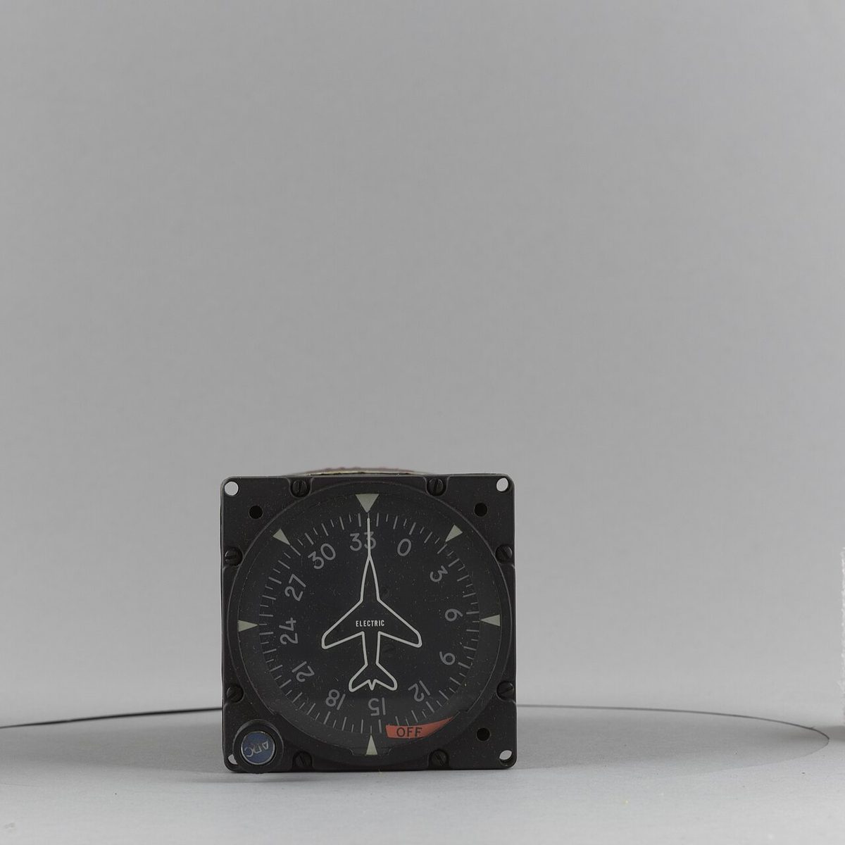
In an air-driven DI, the air jets that spin the rotor also hold its axis in the yawing plane, a coarse correction completed by a finer one acting on the outer gimbal. Electric DIs hold a more constant rotor speed and have a warning flag for loss of power. Air-driven instruments topple beyond about 55° of pitch or roll, electric ones beyond about 85°. In a banked turn the gimbal geometry also produces gimballing error, which follows a double sine curve round a full circle and disappears when the wings are level.

Why a DI drifts
A DI slowly wanders away from the heading it was set to (see gyroscopic principles):
| Source | Cause | Size |
|---|---|---|
| Real wander | Bearing friction, imbalance, manufacturing imperfections | About 1.6° per hour for an air-driven rotor at 10,000 rpm, less for faster and better gyros |
| Earth rate | The Earth turns under the space-fixed axis | 15.04° per hour × sine of latitude: nil at the equator, about 13° per hour at 60°, 15° per hour at the pole |
| Transport wander | Flying east or west changes the direction of the local meridian | Nil at the equator, growing with latitude |
In the northern hemisphere Earth-rate drift makes the reading decrease; in the southern it increases. A latitude nut, an adjustable weight on the inner gimbal, makes the gyro precess at an equal and opposite rate, but only at the latitude for which it is set; flying away from that latitude leaves a growing residual drift (see polar and grid navigation). An air-driven DI whose rotor runs slow, from low suction or a blocked filter, precesses more under the nut's torque and over-corrects.
The practical rule follows: realign the DI with the compass every 10 to 15 minutes, in straight, level, unaccelerated flight. FAA handbooks treat about 3° of drift in 15 minutes as acceptable. Setting it during a turn or an acceleration copies the compass error into the DI. Lined up on the runway, both should read close to the runway's magnetic direction, a useful gross-error check.
Remote indicating compass principle
The direct-reading compass has three limitations: turning and acceleration errors, a magnet that must sit in the cockpit among ferrous metal and electrical equipment, and no output for other systems. The remote indicating magnetic compass, also called the gyro-magnetic compass or slaved gyro compass, removes all three.
It combines a directional gyro, which gives a stable heading free of turning and acceleration errors in the short term, with a magnetic sensor mounted far from the cockpit, which slowly corrects the gyro's drift in the long term. The result, the slaved heading indicator, drives the pilot's horizontal situation indicator (HSI) or compass card, the radio magnetic indicator (RMI) and the autopilot. Heading reaches these through synchros: a transmitter on the heading shaft sets up a field in three stator coils that a receiver in each repeater reproduces and follows.
Flux valve detector
The magnetic sensor is the flux valve, also called the flux detector or flux gate. It is mounted in a wing tip or the fin, the part of the airframe least affected by aircraft magnetism. It hangs on a Hooke's joint that lets it swing about 25° in pitch and roll but not in azimuth, in a sealed case partly filled with oil for damping, so that it stays roughly horizontal and senses the horizontal component of the field.
The detector has three legs 120° apart, each carrying a pick-up coil, with an AC excitation coil at the centre that saturates the legs alternately in opposite directions. With no external field the fluxes cancel and nothing is induced. The Earth's field unbalances them, and by Faraday's law each pick-up coil produces a voltage that depends on the field along its leg. A single leg could not distinguish two headings with the same voltage; three together define the direction uniquely. Their outputs feed three stator coils that recreate the field direction inside the system.
Because it is pendulous, the flux valve is disturbed in turns and accelerations like any compass; the slow slaving keeps those transient errors out of the displayed heading. In glass-cockpit light aircraft a magnetometer does the same job for the attitude and heading reference system.
Slaving and synchronisation
The system compares the recreated magnetic direction with the gyro's heading. A rotor coil turned by the gyro sits in the stator field; when it lies at 90° to the field, the null position, no voltage is induced and the two agree. If the gyro drifts, an error signal appears.
The precession amplifier processes it in three steps. It amplifies the weak AC signal; it phase-detects it, to find whether the gyro has drifted clockwise or anticlockwise; and it rectifies it into DC for the slaving motor, also called the precession motor, which applies a torque to the gyro. The gyro precesses back towards the magnetic heading, at a normal rate of only about 3° per minute. That slowness is deliberate: turns and accelerations are over before the flux valve's transient errors can drag the heading, while the gyro's drift of a few degrees per hour is easily absorbed. In a steady turn gyro and flux valve turn together and no error signal builds up.
A synchronisation annunciator on the compass controller shows the error signal. Continuous small movement either side of centre is normal and proves that slaving is active. A steady deflection means the system needs synchronising or magnetic monitoring has failed.
At start-up the gyro may be 90° away from the magnetic heading, which at 3° per minute would take half an hour to remove. Rapid synchronisation solves this: a spring-loaded switch, or on older systems a mechanical clutch, raises the gain of the precession amplifier so that the heading aligns in seconds. It is also used after a period in free mode.
Free and slaved modes
A FREE/SLAVE switch selects the mode:
- Slaved mode is normal: magnetic monitoring active, heading stable and without long-term drift.
- Free mode, also called DG mode, disconnects the flux valve so that the system acts as a directional gyro. It is used when the magnetic input has failed, and at high magnetic latitudes, where the horizontal field is too weak for the flux valve. The pilot then resets the heading periodically against a known reference, standby compass, INS or GNSS, using a spring-loaded clockwise/anticlockwise switch.
A heading warning flag appears when the flux valve input fails, whatever the switch position; the system is then in effect a free gyro. A steady deflection of the annunciator likewise shows that the system needs synchronising or that magnetic monitoring has failed. Without magnetic monitoring the heading is set by hand against the standby compass, which is accurate only in steady, wings-level, unaccelerated flight.
Warning: the FAA's AIM warns that materials on or under taxiways and ramps can generate magnetic fields strong enough to pull a slaved compass off alignment during taxi, and that the error may not correct itself. Any misalignment should be corrected, following the manufacturer's procedure, before take-off.
Magnetic and true heading reference
Airliners fitted with an inertial reference system normally take heading from it rather than from a flux valve; on the Boeing 737 the IRSs are the only heading source apart from the standby compass. The IRS finds true north by gyrocompassing during its alignment and then maintains true heading; it produces magnetic heading by applying variation from a magnetic variation table stored in the unit, a model of the kind published as the World Magnetic Model. Because variation changes with time, the table is updated periodically, and its accuracy limits where magnetic heading may be used.
Displays therefore carry a MAG/TRUE heading reference. In the EFIS arrangement described in ATPL instrumentation texts, the navigation display in MAP mode references heading and track to magnetic north between 73°N and 65°S and changes automatically to true north outside those latitudes, and a crew MAG/TRUE selector forces true reference anywhere. Type limitations define the areas where magnetic data is invalid:
| Aircraft | Flight manual limitation |
|---|---|
| Airbus A320, all ADIRUs with the same variation table | No valid IR magnetic heading or track north of 73°N between 90°W and 120°W, north of 82°N or south of 60°S; flight beyond is prohibited |
| Airbus A320, one ADIRU with a different table | No valid IR magnetic heading or track north of 60°N between 30°W and 160°W, north of 73°N or south of 55°S; flight beyond is prohibited |
| Boeing 737 | Operations based on magnetic heading or track prohibited where the variation table error exceeds 5°; maximum operating latitude from the tables generally 82°N and 82°S, lower in two longitude bands |
In polar regions crews work in true or grid heading (see polar and grid navigation).
Compass swinging and calibration
A remote indicating compass has far less residual deviation than a direct-reading one, whose residual deviation CS 25.1327 limits to 10° on any heading, but it is still swung. The swing is done on a compass swinging base, a site surveyed to be free of buried cables, ferrous material and other aircraft, whenever components are installed or replaced, after modifications or repairs involving magnetic material or electrical equipment, after a lightning strike or heavy shock, before carrying unusual ferromagnetic loads, after a large change of magnetic latitude and at the intervals of the maintenance programme. A check swing on 8 or 12 headings records the residual deviations.
Before every IFR flight the pilot checks the heading system on the ground: during taxi turns the heading indicator and compass should turn in the right direction, and lined up on the runway both should agree with its magnetic direction.
Frequently asked questions
How often should the heading indicator be reset to the compass?
Every 10 to 15 minutes, and only in straight, level, unaccelerated flight after the compass card has settled, because the compass is accurate only then. Resetting during a turn or a change of speed copies the compass's turning or acceleration error into the heading indicator. FAA handbooks treat a drift of about 3 degrees in 15 minutes as acceptable. A slaved heading indicator corrects itself from its flux valve.
What is a flux valve?
A flux valve, or flux detector, is the magnetic sensor of a remote indicating compass. It has three legs 120 degrees apart, alternately saturated by an AC excitation coil, and pick-up coils in which the Earth's field induces voltages that together give its direction. It is mounted in a wing tip or the fin, away from aircraft magnetism, on a Hooke's joint that lets it swing in pitch and roll but not in azimuth.
What is the difference between free and slaved mode?
In slaved mode the flux valve continuously and slowly corrects the gyro towards magnetic north, at about 3 degrees per minute, so the heading stays stable in manoeuvres and free of long-term drift. In free mode the magnetic input is disconnected and the system acts as a plain directional gyro. It is used when the flux valve has failed and at high magnetic latitudes, and the heading must then be reset by hand.
Why does a directional gyro drift?
It drifts because of real wander, from bearing friction and imbalance, and apparent wander, because its axis stays fixed in space while the Earth turns beneath it. Apparent drift from the Earth's rotation is 15.04 degrees per hour times the sine of the latitude, about 13 degrees per hour at 60 degrees north; in the northern hemisphere the reading decreases. A latitude nut can cancel it at one chosen latitude.
How does an inertial reference system give magnetic heading?
The IRS finds true north itself by gyrocompassing during its ground alignment and then maintains true heading. It converts that to magnetic heading by applying magnetic variation from a table stored in the unit. Near the magnetic poles, where the table is unreliable, magnetic heading is not valid and crews use true heading. The flight manual defines those areas: the A320's limitations, for example, prohibit flight beyond them.
Test yourself on Heading Indicators and Compass Systems
The v1prep banks cover this topic in Instrumentation (022), with a worked explanation for every answer. EASA ATPL, PPL, IR and CPL, the FAA written tests and A320/B737 type ratings.
Start practising →Sources and further reading
- FAA Instrument Flying Handbook (FAA-H-8083-15B), Chapter 5, Flight Instruments (heading indicator and slaved compass systems)
- FAA Pilot's Handbook of Aeronautical Knowledge (FAA-H-8083-25), Chapter 8, Flight Instruments (heading indicator and magnetic compass)
- FAA Aeronautical Information Manual, Chapter 1 Section 1 (1-1-15, slaved compass heading errors from ground flux fields)
- EASA Easy Access Rules for Large Aeroplanes (CS-25), CS 25.1327 Magnetic direction indicator
- NOAA National Centers for Environmental Information, World Magnetic Model
- EASA, Explanatory Note to ED Decision 2018/001/R, Part-FCL theoretical knowledge learning objectives (022 Instrumentation, 061 General Navigation)
Library articles are written for study and exam preparation. They do not replace your aircraft's approved documentation, your operator's procedures or the regulations themselves.