Gyroscopic Principles
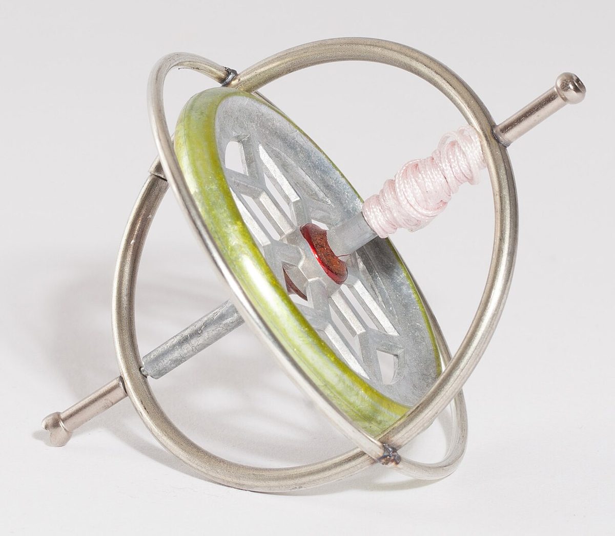
A gyroscope is a rapidly spinning rotor mounted in gimbals so that its spin axis can hold a direction independently of the aircraft. Its rigidity in space and its precession when a force is applied are the basis of the attitude indicator, the heading indicator and the turn indicator.
A gyroscope is a wheel, the rotor, spinning at high speed in a mounting that leaves its spin axis free to point in any direction. Such a rotor keeps its axis pointing the same way in space however the aircraft around it turns, and when it is pushed it responds in a characteristic way, at right angles to the push. Those two properties, rigidity and precession, give the pilot a stable artificial horizon, a heading reference free of the compass's turning and acceleration errors, and a measure of the rate of turn.
Gyro instruments are required for instrument flight: in the United States, 14 CFR 91.205 requires a gyroscopic attitude indicator, a gyroscopic direction indicator and, with some exceptions, a gyroscopic rate-of-turn indicator for IFR. Their errors are equally part of the syllabus, because each one, from drift to topple, follows from the same physics. This article explains that physics; the individual instruments are covered under attitude indicator, heading indicators and turn and slip indicators.
Rigidity and precession
Gyroscopic rigidity, also called rigidity in space or gyroscopic inertia, is the tendency of a spinning rotor to keep its spin axis fixed in direction unless a torque acts on it. It is proportional to the rotor's moment of inertia multiplied by its speed of rotation. Designers therefore concentrate the rotor's mass at the rim and spin it fast.
Gyroscopic precession is the rotor's response to a torque that tries to tilt its axis. The rotor does not move in the direction of the push. It behaves as if the force had been applied at a point 90° further round the rim, in the direction of rotation, and the axis turns accordingly. The rate of precession is directly proportional to the applied torque and inversely proportional to the moment of inertia and the rotor speed: doubling the rotor speed halves the precession caused by the same torque.

Rigidity and precession are two sides of the same property. A rotor with high rigidity precesses little, which is what an instrument that must hold a reference needs; a rotor that precesses readily is what an instrument that measures turning needs. Precession is also familiar from propellers: on an aeroplane whose propeller turns clockwise seen from the cockpit, pitching the nose up produces a yaw to the right (see propeller torque and slipstream effects).
Gimbals and degrees of freedom
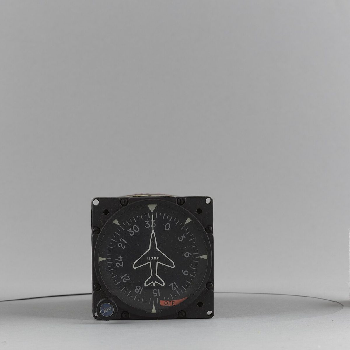
A gimbal is a ring pivoted so that the rotor, or another gimbal, can turn inside it. A rotor spinning in an inner gimbal, which is itself pivoted in an outer gimbal, can hold its axis steady while the case rotates around it. In a typical heading indicator the rotor axis, the inner gimbal axis and the outer gimbal axis are mutually at right angles, and the outer gimbal can turn through a full 360°.
A degree of freedom (DOF) is an axis about which the spin axis is free to move relative to the case. EASA texts do not count the spin axis itself, so a gyro with two gimbals has two degrees of freedom and one with a single gimbal has one; some other texts count the spin axis and quote three and two. The two-gimbal gyro holds a direction; the single-gimbal gyro can only precess about its one free axis, which is what makes it useful for measuring rates.
A Hooke's joint, the universal joint of mechanical engineering, gives two axes of freedom in a similar way. The best-known example in instruments is the flux valve of a remote-indicating compass, hung on a Hooke's joint so that it can swing about 25° in pitch and roll while staying fixed in azimuth (see magnetic compass).
Space, tied and earth gyros
Gyros that measure angles are classified by the reference to which their spin axis is held:
| Type | Spin axis held to | Example |
|---|---|---|
| Space gyro | Nothing: fixed in inertial space | High-grade gyros of inertial systems |
| Tied gyro | A chosen reference, by an external control | Heading indicator (axis kept in the yawing plane) |
| Earth gyro | The local vertical, by gravity-sensing control | Attitude indicator |
A space gyro has freedom in all planes and no control acting on it, so its axis stays fixed in space apart from its own imperfections. A tied gyro is continually brought back to a chosen reference; the heading indicator's rotor axis is kept in the aircraft's yawing plane, and in a remote-indicating compass the gyro is also slaved to magnetic north. An earth gyro is a tied gyro whose reference is the direction of gravity. The attitude indicator is the classic example: pendulous vanes in an air-driven instrument, or mercury switches and torque motors in an electric one, sense any tilt and apply torques whose precession returns the spin axis to the vertical. That erection is deliberately slow, which is why sustained accelerations and turns can pull the gyro towards a false vertical. Every earth gyro is a tied gyro, but not every tied gyro is an earth gyro.
Rate and displacement gyros
A displacement gyro measures an angle: pitch and bank in the attitude indicator, heading change in the heading indicator. It has two gimbals, relies on rigidity and is spun fast.
A rate gyro measures a rate of rotation. It has a single gimbal, restrained by a spring. When the aircraft turns, the turn forces the rotor to precess about its free axis, tilting the gimbal until the spring's resistance produces a second precession that exactly matches the rate of turn. The tilt is therefore proportional to the rate of turn, and the instrument is calibrated so that a rate one turn, 3° per second, reaches the marker. Because it measures by precession, a rate gyro is spun more slowly than a displacement gyro; because it has only one gimbal, it cannot topple. Rate gyros drive the turn indicator and the yaw damper. The turn coordinator's gimbal is canted about 30°, so that it senses roll as well as yaw.
Rotors are driven by air or electricity. Air-driven gyros, powered by an engine-driven vacuum pump, lose rotor speed and rigidity if the suction falls, through a failing pump, a clogged filter or reduced suction at high altitude. Electric gyros are heavier and dearer but spin faster, with more precisely controlled speed: ATPL texts quote about 22,500 rpm for an electric attitude indicator against about 15,000 rpm for an air-driven one. Light aircraft often use vacuum-driven attitude and heading indicators with an electric turn coordinator, so that one power failure cannot remove every gyro. A gyro that loses power spins down slowly and can show a plausible but wrong picture for several minutes before it is obviously failed. Ring laser and fibre optic gyros used in inertial systems have no rotor at all; they sense rotation optically (see inertial navigation).
Real and apparent drift
Any movement of the spin axis away from its reference is called wander. Wander in the horizontal plane is drift; wander in the vertical plane is topple. A gyro with a horizontal spin axis can both drift and topple; a vertical-axis gyro, such as the attitude indicator's, can only topple.
Real wander, also called random wander, is a genuine movement of the spin axis in space. It comes from manufacturing imperfections: friction in the rotor bearings and gimbal pivots, rotor imbalance and unbalanced gimbals. Better engineering reduces it, at a cost that must be justified by the application.
Apparent wander is the gyro holding its direction in space while the observer's reference moves. The heading indicator is read against the local meridian, and the local meridian changes direction in space for two reasons: the earth rotates, and the aircraft moves east or west across meridians that converge towards the poles. The result is apparent gyro drift even from a perfect gyro.
Earth rate and transport wander
Earth rate is the apparent drift caused by the earth's rotation. In azimuth it is 15° per hour × sin(latitude), more precisely 15.04° because the sidereal day counts: zero at the equator, about 13° per hour at 60° latitude and 15° per hour at the poles. In the northern hemisphere an uncorrected heading indicator's readings decrease with time; in the southern hemisphere they increase.
Earth rate compensation in a heading indicator is by a latitude nut, a small adjustable weight on the inner gimbal. Screwed off centre, it applies a steady torque whose precession produces a real drift equal and opposite to the earth rate at one chosen latitude. The correction is exact only there. Flying away from that latitude increases the residual drift; in the northern hemisphere, flying north of it makes the readings decrease and flying south makes them increase. Because the precession caused by the nut depends on rotor speed, an air-driven gyro running slow or fast is over- or under-corrected. Inertial systems compensate for earth rate by computation or by torquing their gyros.
Transport wander arises from flying east or west at any latitude other than the equator. Its rate in degrees per hour is (east-west groundspeed in knots ÷ 60) × tan(latitude); over a whole flight it equals the change of longitude × sin(mean latitude), the convergency between departure and destination meridians. At 45°, where tan equals 1, a groundspeed of 300 kt due east gives 5° per hour. Flying east adds to the effect of earth rate and flying west subtracts from it, in either hemisphere: in the northern hemisphere, eastbound flight makes an uncorrected gyro's readings decrease faster.
The total drift of a heading indicator is the sum of real wander, earth rate, the latitude nut correction and transport wander. In practice the pilot resets it to the magnetic compass about every 10 to 15 minutes, in straight, level, unaccelerated flight when the compass is reliable; the FAA considers about 3° of drift in 15 minutes acceptable. Slaved gyro compasses make this correction continuously from a flux valve.
Exam tip: earth rate uses the sine of latitude and transport wander the tangent. Both are zero at the equator.
Topple, gimbal lock and gimballing error
Gyro topple occurs when the aircraft's attitude drives a gimbal against its stops. The gyro can no longer keep its orientation, the torque from the stops makes it precess violently, and the indication spins or tumbles. Gyro topple limits depend on the instrument: ATPL texts quote 55° of pitch or roll for an air-driven heading indicator and 85° for an electric one; older attitude indicators 60° in pitch and 110° in roll, modern ones 85° in pitch with full freedom in roll. An air-driven attitude indicator that has toppled may take 10 to 15 minutes to re-erect; an electric one with a fast erection facility takes seconds.
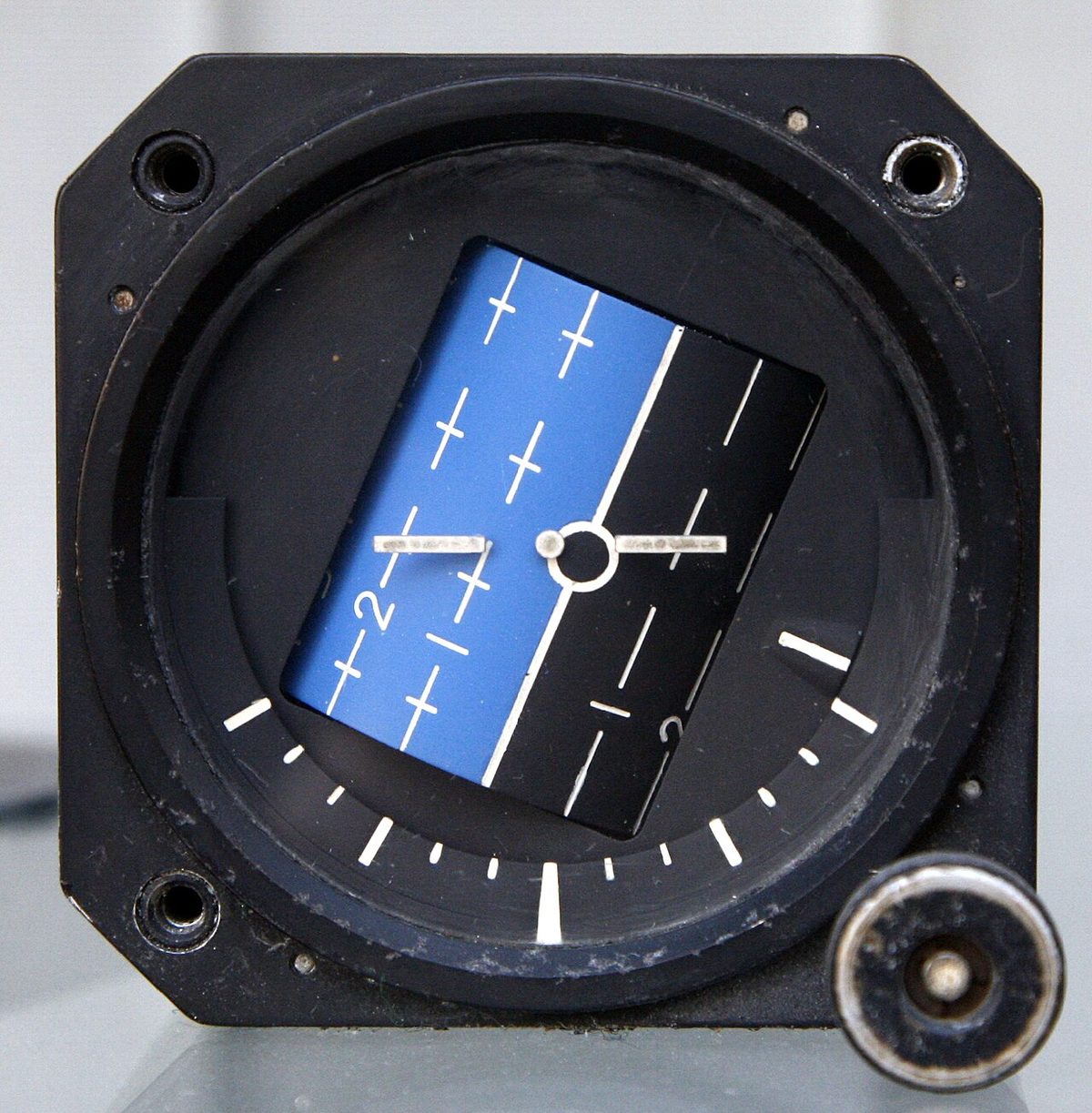
Gimbal lock occurs when the aircraft's attitude brings two gimbal axes into line, as can happen near 90° of bank or pitch. The gyro loses a degree of freedom, and any further rotation about the lost axis is forced onto the rotor, which then topples. Aerobatic instruments and modern attitude systems avoid it with a fourth gimbal or a mechanism that flips the outer gimbal through 180°.
Gimballing error affects the heading indicator in banked flight. When the aircraft banks, the geometry of the gimbals forces the outer gimbal, which carries the heading card, to move relative to the case even though the rotor axis stays fixed in space. Plotted against heading through a 360° turn, the error forms a rough double sine curve, zero on four headings. It is small at moderate bank angles and disappears when the wings are levelled.
Caging a gyro
A caging device locks a gyro's gimbals in a fixed position relative to the case. On a heading indicator, pushing the caging knob locks the inner gimbal at 90° to the outer gimbal and engages a gear with the outer gimbal, so that turning the knob rotates the gyro and card together. Gyro caging is used to synchronise the heading indicator with the magnetic compass, to protect the gyro before manoeuvres beyond its topple limits and to re-erect it quickly after it has toppled. Pulling the knob out releases the gyro.
Some older attitude indicators also have a caging knob. Where one is fitted, the gyro should be uncaged at least five minutes before take-off so that the rotor reaches full speed and the spin axis settles on the true vertical.
Frequently asked questions
What are the two gyroscopic principles used in flight instruments?
Rigidity in space and precession. A spinning rotor resists any change in the direction of its spin axis, which lets the attitude indicator and heading indicator hold a stable reference while the aircraft moves around them. When a force is applied, the rotor responds as if the force had been applied 90° further round the rim in the direction of rotation; the turn indicator measures this precession to show the rate of turn.
How do you calculate earth rate for a directional gyro?
Apparent drift due to the earth's rotation is 15° per hour multiplied by the sine of the latitude; the precise figure is 15.04°, because the sidereal day is used. It is zero at the equator and a full 15° per hour at the poles, and about 13° per hour at 60° latitude. In the northern hemisphere an uncorrected directional gyro's readings decrease with time; in the southern hemisphere they increase.
What is the difference between real wander and apparent wander?
Real wander is a genuine movement of the gyro's spin axis in space, caused by imperfections such as bearing friction, gimbal friction and rotor imbalance. Apparent wander is an apparent movement seen by an observer whose own reference moves while the gyro stays fixed in space. Its two causes are the earth's rotation, called earth rate, and flight east or west across converging meridians, called transport wander.
What is gimbal lock?
Gimbal lock occurs when the aircraft's attitude brings two gimbal axes into line, so that the gyro loses one of its degrees of freedom. Any further rotation about the lost axis must then be passed to the rotor, which is forced out of its orientation and precesses violently, and the gyro topples. Instruments built for aerobatics and modern attitude systems avoid it with a fourth gimbal or a mechanism that flips the outer gimbal.
What does caging a gyro mean?
Caging locks a gyro's gimbals in a fixed position relative to the instrument case. On a directional gyro, pushing the caging knob locks the inner gimbal at 90° to the outer gimbal and engages a gear, so turning the knob sets the heading card to match the magnetic compass. Caging also protects the gyro before manoeuvres beyond its topple limits and re-erects it quickly after it has toppled.
Test yourself on Gyroscopic Principles
The v1prep banks cover this topic in Instrumentation (022), with a worked explanation for every answer. EASA ATPL, PPL, IR and CPL, the FAA written tests and A320/B737 type ratings.
Start practising →Sources and further reading
- FAA Pilot's Handbook of Aeronautical Knowledge (FAA-H-8083-25), Chapter 8, Flight Instruments
- FAA Instrument Flying Handbook (FAA-H-8083-15B), Chapter 5, Flight Instruments
- EASA, Explanatory Note to ED Decision 2018/001/R, Part-FCL theoretical knowledge learning objectives (022 Instrumentation)
- 14 CFR 91.205, Powered civil aircraft with standard category U.S. airworthiness certificates, instrument and equipment requirements
Library articles are written for study and exam preparation. They do not replace your aircraft's approved documentation, your operator's procedures or the regulations themselves.